Rear – Toa EV-20R User Manual
Page 6
6
[Rear]
FOR HOME OR OFFICE USE
with FCC standards
Tested to comply
N29
4s
2s
ON
DELAY
INTERVAL
TIMER
DC IN
GND
SIGNAL
1h 30m
10m
1m
30s
0s
5m
5s
10s
OUT
24V
STOP
4
3
2
1
PLAY 1 – 4 / STOP
LINE IN
LINE OUT
DC IN
H
C
E
E
C
H
BUSY
SPKR
Class 2 Wiring / 8 – 16 Ω
ENGINEERED IN JAPAN ASSEMBLED IN TAIWAN
TOA Corporation
SOUND REPEATER EV-20R
24V 400mA
11 12 13
14 15
16
17
18
19
20
21
22
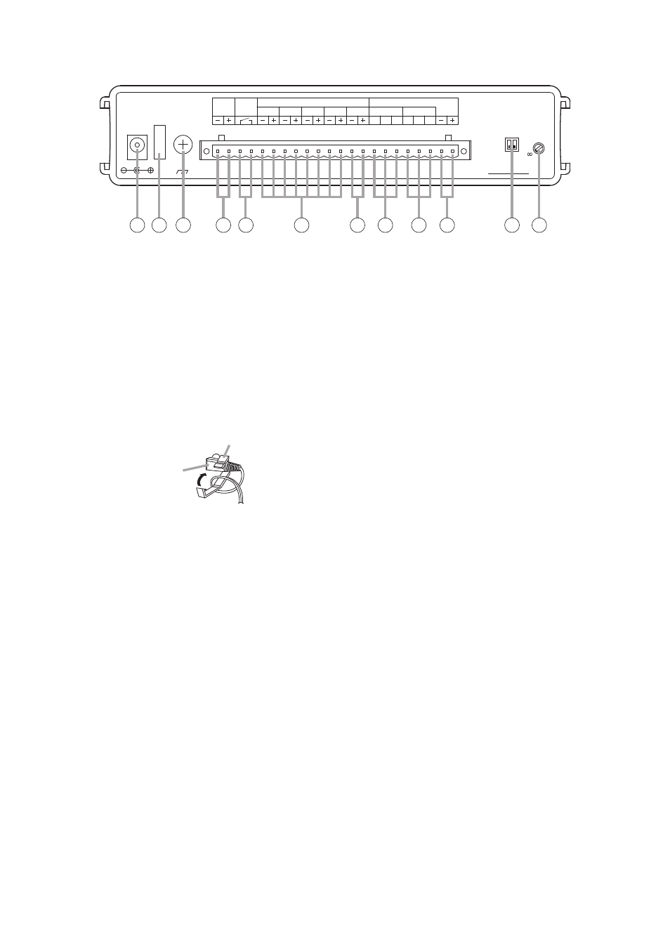
11. AC Adapter Input Terminal [DC IN]
Connects to the optional AD-246 AC adapter or
its equivalent.
Tip: When this terminal and the DC Power Input
terminal (14) are simultaneously used, the
terminal receiving the higher voltage takes
precedence.
12. Cord Clamp
Wrap the AC adapter cord around this clamp to
prevent the plug from pulling out.
13.Ground Terminal [SIGNAL GND]
Connect this terminal to the ground terminals of
the amplifier or other connected equipment.
14. DC Power Input Terminal [DC IN]
Connects to the 24 V DC power supply.
15. Busy Output Terminal [BUSY]
Following message activation, this terminal
remains at 'make' until playback is completed.
When repeat broadcast mode is selected by the
Playback Interval Setting switch (22), the busy
output during the set time intervals (except for "0
s" and "
∞
" settings) can be set to "Make" (ON) or
"Break" (OFF) with the Delay Time Setting switch
(21). (Refer to p. 13.)
Contact capacity: 30 V DC, 0.5 A
16. Start Input Terminal [PLAY]
Triggers message playback when closed.
Contact: No-voltage 'make' contact, triggered by
pulse of over 200 ms in length.
17. Stop Input Terminal [STOP]
Stops playback when closed.
Contact: No-voltage 'make' contact, triggered by
pulse of over 200 ms in length.
18. Line Input Terminal [LINE IN]
Connects to external music playback equipment
for broadcast. When the EV-20R's message
broadcast is started during external equipment
broadcast, the message broadcast takes
precedence.
0 dB, 10 kΩ, unbalanced. (Refer to p. 13.)
19. Line Output Terminal [LINE OUT]
Provides output of playback messages or signals
input to the Line Input terminal (18).
0 dB, 600 Ω, unbalanced. (Refer to p. 13.)
Line Input terminal signals are not output during
message playback.
20. Speaker Output Terminal [SPKR]
Connect only low-impedance speakers to this
terminal.
21. Delay Time Setting Switch [DELAY]
Sets the delay time between message activation
and actual playback start. Also sets the busy
output during the time intervals (except for "0 s"
and "
∞
" settings) to "Make" (ON) or "Break"
(OFF) when repeat broadcast mode is selected
by the Playback Interval Setting switch (22).
Setting the busy output to OFF makes the delay
time 0 seconds. (Refer to p. 13.)
The delay time is factory-preset to 0 seconds,
and the busy output during intervals between
repeated broadcasts to "Make" (ON).
(Refer to p. 13.).
22. Playback Interval Setting Switch
[INTERVAL TIMER]
Sets playback time intervals between repeated
broadcasts of the same message.
(Refer to p. 14.)
This switch is factory-preset to "
∞
" (Repeat
broadcasts disabled).
Cord clamp
AC adapter plug