Toa EV-20R User Manual
Page 12
12
9.2. Connections to the Rear-Mounted Connectors
Notes
• Use the appropriate type of screwdriver for the connector wiring screws.
• When using stranded or shielded cable, do not solder the stripped and exposed ends.
When the cable is clamped, the solder becomes crushed, increasing contact resistance and possibly
resulting in an extreme rise in cable joint temperature.
Conductor cross-sectional area
0.5 – 1.5 mm
2
AWG
AWG24 – 16
Cable Type (Stranded Cable)
Maximum Distance
0.5 – 1.5 mm
2
20 m
Tighten
Loosen
Connector
(Accessory)
Fixing screw
To unit's rear panel-
mounted socket
Terminal screw
Flat-blade screwdriver
1
2
3
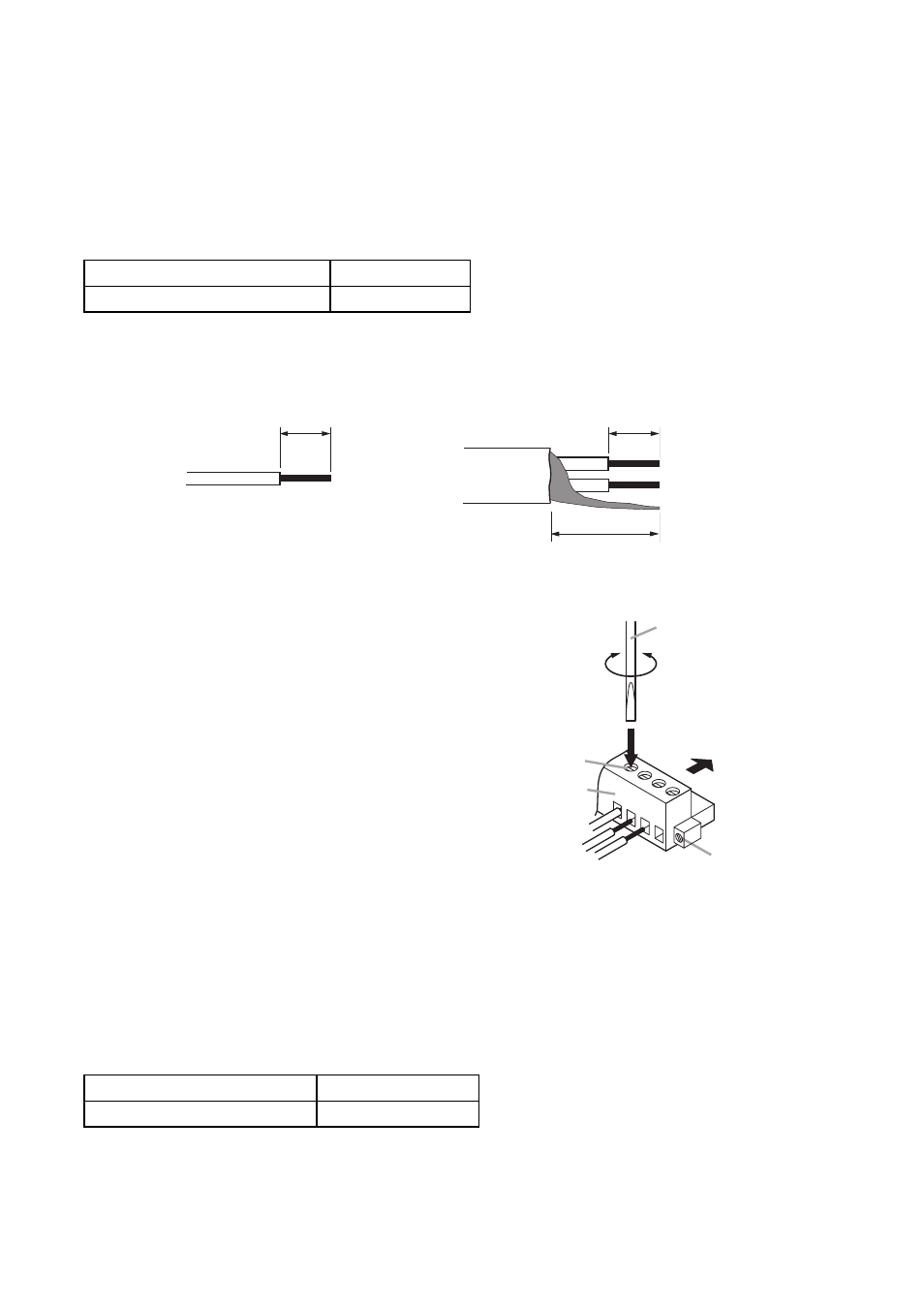
Solid and stranded cables
Shielded cable
6 mm
6 mm
15 mm
9.2.1. Matching cable size
9.2.2. Stripped cable end
9.2.3. Cable connections
9.2.4. Maximum speaker output cable distance
Step 1. Loosen the terminal screw to insert the cable
into the connector, then retighten the screw.
Note
Tug lightly on the cable to be sure that it does
not pull free. If the cable pulls free, loosen the
terminal screw again and reconnect from the
beginning.
Step 2. Insert the connector into the rear-mounted
socket.
Step 3. Tighten the fixing screw.
Note
Take care not to reverse Steps 1 and 2.
When tightening the terminal screw, force is applied to
the connector pins on the internal circuit board,
possibly resulting in poor contact.
Refer to the following table for the distance of the cable to be connected to the Speaker Output terminal.