Test input – TeeJet LH 4000 User Manual
Page 39
LH 4000 O
PERATORS MANUAL
LH A
GRO
39
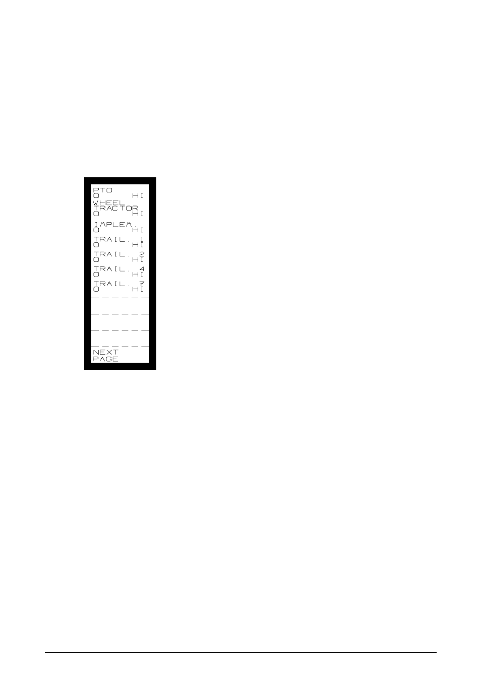
TEST INPUT
Should you observe any malfunction, conduct a test of all circuits and sensors with
the test-program.
The Screen:
Each text string has a "counter" shown at the L/H side. The figure must change
each time a "pulse" (signal) is received.
The R/H side shows the actual status: "HI" or "LO".
The individual input "ports":
PTO:
Signal from the PTO-sensor.
WHEEL
TRACTOR:
Signal from the wheel sensor.
IMPLEMENT: Area override signal. (Tractor)
TRAIL 1:
Signal from pressure sensor. (if
applicable)
TRAIL 2:
Signal from the spray-flowmeter.
TRAIL 4:
Signal from wheel-sensor on
implement (if applicable)
TRAIL 7:
"Override" signal. (e.g. pray-valve)
BOOM 1 TO 9: Status of boom-sections.
See also other documents in the category TeeJet Computers:
- Sentry 6140 (16 pages)
- 801 flowmeter (2 pages)
- GPS Speed Sensor (2 pages)
- IC18 SPREADER JOB COMPUTER (47 pages)
- IC18 SPREADER JOB COMPUTER (32 pages)
- IC18 SPRAYER JOB COMPUTER (43 pages)
- IC18 SPRAYER JOB COMPUTER (68 pages)
- IC18 NH3 JOB COMPUTER (63 pages)
- BOOMPILOT JOB COMPUTER (21 pages)
- BOOMPILOT JOB COMPUTER (32 pages)
- MATRIX 570VT Software version 1.00 (12 pages)
- MATRIX 570VT Software version 1.00 (20 pages)
- MT 600 Piston Injection Pump (6 pages)
- BoomPilot (2 pages)
- BoomPilot Pro Metric (2 pages)
- BoomPilot Pro (2 pages)
- 500 SLURRY COMPUTER (30 pages)
- 70 Series Speed Area Monitor (2 pages)
- 70 Series EPC - Manual Pump (4 pages)
- 70 Series Fill Flow (2 pages)
- 70 Series Flow Volume Monitor (2 pages)
- ARC-6000 (50 pages)
- TASC-6000 (78 pages)
- TASC-6100 (86 pages)
- TASC-6200 (50 pages)
- TASC-6200 (45 pages)
- TASC DATA LOGGER (17 pages)
- TASC PRINTER MODULE (8 pages)
- TASC-6000 Supplement (9 pages)
- 744A Sprayer Control (14 pages)
- 744E AUTO BOOM SECTION CONTROL (8 pages)
- 744E SPRAYER CONTROL (16 pages)
- 814-AB Airblast Sprayer Monitor (15 pages)
- 834 Sprayer Control (15 pages)
- 834 Sprayer Control L2.12 (15 pages)
- 834-P Sprayer Control (18 pages)
- 844 Sprayer Control (44 pages)
- 844 Operations Mini (2 pages)
- 844-AB Sprayer Control (24 pages)
- 844-E Sprayer Control (36 pages)
- 844-R Speed Compensated Application Control (32 pages)
- 854 Sprayer Control (52 pages)
- 026 – 73 AddFlow (8 pages)
- LH 3000 (24 pages)