Fig. 22 — space temperature averaging wiring – Carrier WEATHERMAKER 48AJ User Manual
Page 30
30
Staged Gas Control Option Thermistors — If the unit is
equipped with the staged gas heat option, supply-air ther-
mistors must be installed. Three supply-air thermistors are
shipped with staged gas units and are inside the heating sec-
tion. The supply-air thermistors should be located in the supply
duct with the following criteria:
• Downstream of the heat exchanger cells
• Equally spaced as far as possible from the heat
exchanger cells
• In a duct location where none of the supply-air ther-
mistors are within sight of the heat exchanger cells
• In a duct location with good mixed supply-air portion of
the unit.
SPT (Space Temperature Sensor) — For constant volume ap-
plications the ComfortLink™ controls can also be used with
T55 and T56 space temperature sensors that use a 10K ther-
mistor. The T56 sensor also has the capability for a config-
urable temperature set point offset. For variable air volume ap-
plications only the T55 sensor can be used.
Install sensor according to the installation instructions
included with accessory sensor. Locate sensor assembly on a
solid interior wall in the conditioned space to sense average
temperature.
Run wiring to the space sensor as shown in Fig. 21.
Note that when the remote sensor is used, the red jumper
wires provided must be connected from TB4 terminal 4 to 5
and TB4 terminal 5 to 1.
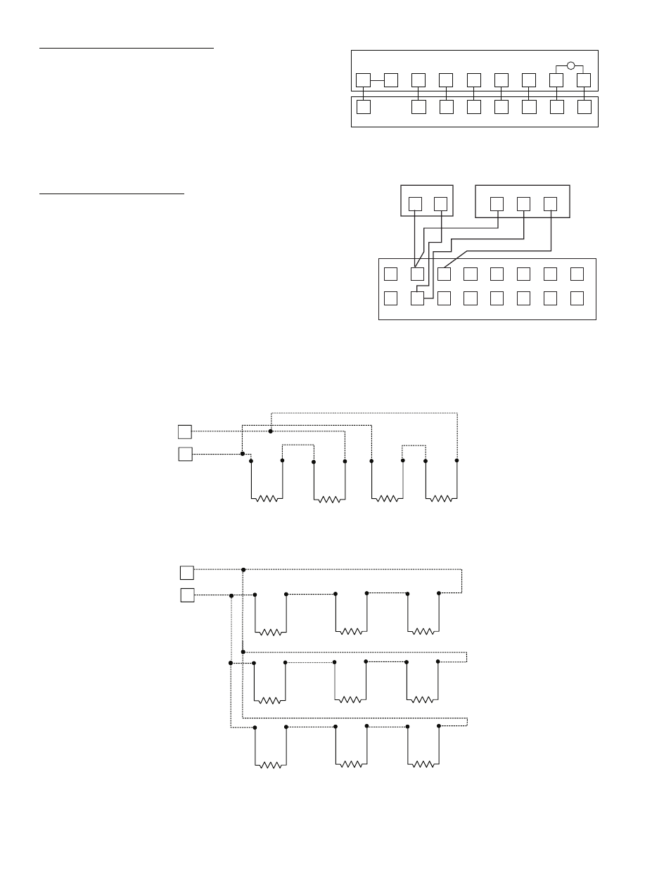
Both the T55 and T56 have a CCN communications port and
this should be wired to the CCN Communications TB3 board if
it is desired to have access to the CCN through the sensor. If
more than one T-55 sensor is being used and averaged, sensors
must be wired in multiples of 4 or 9 as shown in Fig. 22.
T1
T2
1
2
4
3
5
6
7
8
9
10
11
12
13
14
15
16
TH
C
SN
T56 SPT
T55 SPT
UNIT
TB5
TB4
Fig. 20 — Field Control Thermostat Wiring
Fig. 21 — Space Temperature Sensor Wiring
R
Y1
Y2
W1
W2
G
C
X
R
Y1
Y2
W1
W2
G
C
X
FIELD-SUPPLIED THERMOSTAT
LIGHT
RC
1
2
3
4
5
6
7
8
a48-8243
a48-6854
3
4
RED
BLK
TB5
3
4
TB5
SENSOR 1
SENSOR 2
SENSOR 3
SENSOR 4
SENSOR 1
SENSOR 2
SENSOR 3
SENSOR 4
SENSOR 5
SENSOR 6
SENSOR 7
SENSOR 8
SENSOR 9
SPACE TEMPERATURE AVERAGING (4 SENSOR APPLICATION)
SPACE TEMPERATURE AVERAGING (9 SENSOR APPLICATION)
NOTE: Use T55 sensor only.
Fig. 22 — Space Temperature Averaging Wiring
a48-6855