Carrier WEATHERMAKER 48AJ User Manual
Page 19
19
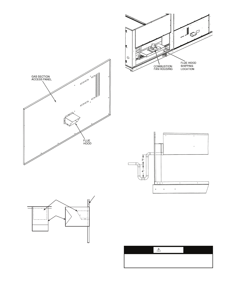
Step 5 — Install Flue Hood
48AJ,AK,AW,AY020-050 UNITS — Flue hood is shipped
inside gas section of unit. To install, secure flue hood to access
panel. See Fig. 14.
48AJ,AK,AW,AY051 AND 060 UNITS — Flue hood and
wind baffle are shipped inside gas section of unit. To install, se-
cure flue hood to access panel. Install the two pieces of the
wind baffle over the flue hood. See Fig. 15.
NOTE: When properly installed, flue hood will line up with
combustion fan housing. See Fig. 16.
Step 6 — Trap Condensate Drain —
See Fig. 4-9
for drain location. Condensate drain is open to atmosphere and
must be trapped. Install a trapped drain at the drain location.
One 1-in. FPT coupling is provided inside the unit evaporator
section for condensate drain connection. A trap at least 4-in.
deep must be used. See Fig. 17. Trap must be installed to pre-
vent freeze-up.
Condensate pans are sloped so that water will completely
drain from the condensate pan to comply with indoor air quali-
ty guidelines. The condensate drain pans are not insulated.
Step 7 — Install Gas Piping —
Unit is equipped for
use with natural gas. Installation must conform with local
building codes or, in the absence of local codes, with the Na-
tional Fuel Gas Code, ANSI Z223.1.
Install manual gas shutoff valve with a
1
/
8
-in. NPT pressure
tap for test gage connection at unit. Field gas piping must in-
clude sediment trap and union. See Fig. 18. An
1
/
8
-in. NPT is
also located on the gas manifold adjacent to the gas valve.
WARNING
Do not pressure test gas supply while connected to unit.
Always disconnect union before servicing. Serious injury
could result.
FLUE HOOD
GAS SECTION
ACCESS PANEL
WIND
BAFFLE
TOP VIEW
SIDE VIEW
Fig. 14 — Flue Hood Location
(48AJ,AK,AW,AY020-050 Units)
Fig. 15 — Flue Hood Location
(48AJ,AK,AW,AY051 and 060 Units)
a48-3712
a48-4076
Fig. 16 — Combustion Fan Housing Location
(48AJ,AK,AW,AY020-050 Shown)
a48-3823
Fig. 17 — Condensate Drain Trap Piping Details
(Typical Roof Curb or Slab Mount Shown)
a48-3714