Carrier WEATHERMAKER 48AJ User Manual
Page 15
15
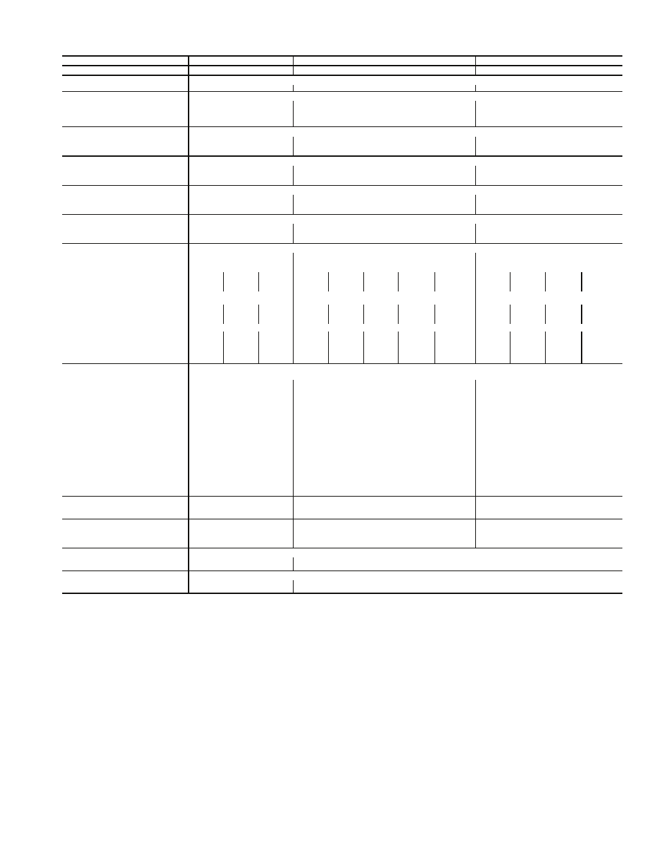
Table 1 — Physical Data — 48AJ,AK,AW,AY Units (cont)
LEGEND
*Sizes 020-040: Circuit 1 uses the lower portion of condenser coil, Circuit 2 uses the upper
portion.
Sizes 041-060: Circuit 1 uses the left condenser coil, Circuit 2 the right. All units have
intertwined evaporator coils.
†Rollout switch is manual reset.
UNIT 48AJ,AK,AW,AY
050
051
060
NOMINAL CAPACITY (tons)
50
50
60
BASE UNIT
See Operating Weights Table
OPERATING WEIGHT (lb)
COMPRESSOR
Quantity ... Type (Ckt 1/Ckt 2)
2…SM125/1…SM125,
1…SM175
2…SM125/2…SM125
1..SM160,1..SM175/
1..SM160,1..SM175
Number of Refrigerant Circuits
2
2
2
Oil (oz) (Ckt 1, Ckt 2)
Precharged
Precharged
Precharged
REFRIGERANT TYPE
R-22
Operating Charge (lb-oz)
Circuit 1
64-4
98-0
81-0
Circuit 2
58-8
98-0
81-0
CONDENSER COIL*
Internally Enhanced,
3
/
8
″ Copper Tubes, Aluminum Lanced, Aluminum Pre-Coated, or Copper Plate Fins
Quantity
2
2
2
Rows ... Fins/in.
4 ... 15
4…15
4…15
Total Face Area (sq ft)
66.7
100
100
CONDENSER FAN
Propeller Type
Nominal Cfm
25,600
38,400
38,400
Quantity... Diameter (in.)
4 ... 30
6...30
6 ... 30
Motor Hp
1
1
1
EVAPORATOR COIL
Internally Enhanced Copper Tubes, Aluminum Plate Fins with Intertwined Circuits
Tube Size (in.)
1
/
2
1
/
2
1
/
2
Rows ... Fins/in.
6 ... 16
4...17
4 ... 17
Total Face Area (sq ft)
31.3
48.1
48.1
EVAPORATOR FAN
Centrifugal Type
Quantity ... Size (in.)
2 ... 20 X 15
3...20 X 15
3 ... 20 X 15
Type Drive
Belt
Belt
Belt
Nominal Cfm
20,000
20,000
24,000
Motor Hp
20
25
30
20
25
30
40
(High Eff.)
40
(Prem. Eff.)
25
30
40
(High Eff.)
40
(Prem. Eff.)
Motor Frame Size
256T
284T
286T
256T
284T
286T
324T
324T
284T
286T
324T
324T
Motor Bearing Type
Ball
Ball
Ball
Maximum Allowable Rpm
1300
1200
1200
Motor Pulley Pitch Diameter (in.)
5.7
6.2
6.7
5.9
5.3
5.9
6.5
9.5
5.3
5.9
6.5
9.5
Nominal Motor Shaft Diameter (in.)
1
5
/
8
1
7
/
8
1
7
/
8
1
5
/
8
1
7
/
8
1
7
/
8
2
1
/
8
2
1
/
8
1
7
/
8
1
7
/
8
2
1
/
8
2
1
/
8
Fan Pulley Pitch Diameter (in.)
9.5
9.5
9.5
11.1
9.1
9.5
9.5
13.7
9.1
9.5
9.5
13.7
Nominal Fan Shaft Diameter (in.)
1
15
/
16
1
15
/
16
1
15
/
16
Belt Quantity
2
2
2
2
3
3
3
2
3
3
3
2
Belt Type
5VX550
5VX570
5VX570
5VX560
5VX530
5VX550
5VX570
5VX650
5VX530
5VX550
5VX570
5VX650
Belt Length (in.)
55
57
57
56
53
55
57
65
53
55
57
65
Pulley Center Line Distance (in.)
15.0-17.9
14.6-17.6
14.6-17.6
15.0-17.9
15.2-17.5
14.7-17.2
14.2-17.0
14.2-17.0
15.2-17.5
14.7-17.2
14.2-17.0
14.2-17.0
Factory Speed Setting (rpm)
1061
1154
1249
930
1019
1086
1197
1214
1019
1086
1197
1214
FURNACE SECTION
Supply Line Pressure Range
5.0-in. wg min/13.5-in. wg max.
Rollout Switch Cutout
Temp (F)†
225
225
225
Burner Orifice Diameter (in ...drill size)
Natural Gas
Std
.120 ... 31
.120...31
.120 ... 31
Liquid Propane
Alt
.096 ... 41
.096...41
.096 ... 41
Thermostat Heat Anticipator Setting
Stage 1 (amps)
0.24
0.1
0.36
Stage 2 (amps)
0.13
0.1
0.13
Gas Input (Btuh) Stage 1
(Low Heat/High Heat)
300,000/600,000
582,000/873,000
582,000/873,000
Stage 2
(Low Heat/High Heat)
400,000/800,000
776,000/1,164,000
776,000/1,164,000
Efficiency (Steady State) (%)
82
82
82
Temperature Rise Range
10-40/30-60
10-40/30-60
10-40/30-60
Manifold Pressure (in. wg)
Natural Gas
Std
3.5
3.3
3.3
Liquid Propane
Alt
3.5
3.3
3.3
Gas Valve Quantity
2
3
3
HIGH-PRESSURE SWITCH (psig)
Cutout
426
426
426
Reset (Auto.)
320
320
320
MIXED-AIR FILTERS
Quantity ... Size (in.) Standard
10 ... 20 x 24 x 2
16...20 x 24 x 2
8...20 x 20 x 4
8...20 x 24 x 4
16 ... 20 x 24 x 2
Pleated
5 ... 20 x 20 x 4
5 ... 20 x 24 x 4
8 ... 20 x 20 x 4
8 ... 20 x 24 x 4
OUTDOOR-AIR FILTERS
Quantity...Size (in.)
8...16 x 25 x 2
4...20 x 25 x 2
12...16 x 25 x 2
6...20 x 25 x 2
POWER EXHAUST
Direct Drive, Single-Phase Motors (Factory-Wired for High Speed Operation), Forward-Curved Fan Wheels with Backdraft Dampers on Each Fan Housing
Motor, Quantity...Hp
4...1
11 x 10
6...1
11 x 10
Fan, Diameter...Width (in.)
Al
— Aluminum
Cu
— Copper