Back panel, 2 back panel – ScanTool 5100 ECUsim User Manual
Page 7
ECUsim™ 5100 User Guide
7
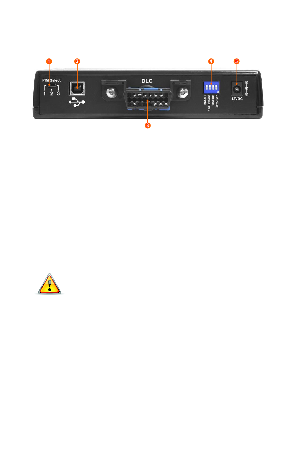
2.2 Back Panel
1.
PIM Select switch
2.
USB connector
3.
Diagnostic Link Connector (DLC)
4.
Configuration DIP switch
a. PIM ALL. Down position: makes all three PIMs active at the
same time. Up position: PIM selection is controlled by the
PIM Select switch
b. 5BAUD/FAST. Selects the type of initialization for
ISO 14230-4. Down: 5 baud init, up: fast init.
c. 11/29 BIT. Selects the CAN frame ID type. Down: 11-bit, up:
29-bit.
d. 250K/500K. Selects the CAN baud rate. Down: 250 kbps, up:
500 kbps.
5.
Power jack (12 VDC)
Use only the provided power supply to power the simulator.
Using a different power supply may cause permanent damage
which is not covered under the warranty.