User interface, Front panel, 0 user interface – ScanTool 5100 ECUsim User Manual
Page 6: 1 front panel
6
ECUsim™ 5100 User Guide
2.0 User Interface
ECUsim 5100 can be used as a stand alone simulator, or in conjunction with a
PC. It features a number of interface elements on both the front and back of
the unit.
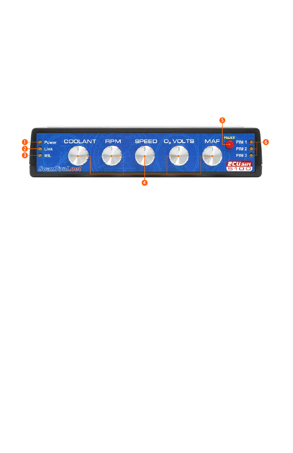
2.1 Front Panel
1.
Power LED
2.
Link LED
The function of this LED depends on the protocol in use:
a. ISO 9141-2 and ISO 14230-4 protocols: the LED is on while at
least one ECU is initialized. The LED dims when an OBD
message is received.
b. J1850 and CAN protocols: the LED blinks when an OBD
message is received.
3.
Malfunction Indicator Light
4.
Knobs
assigned to the five commonly used Mode 1 PIDs.
5.
FAULT button
When pressed, the following happens:
a. Set MIL and number of stored DTCs (Mode 1, PID 01)
b. Generate pending, stored, and permanent* DTCs
c. Generate freeze frame data
6.
PIM indicators
a. OFF: PIM not present
b. RED: PIM is present, not selected
c. GREEN: PIM is active
* SAE J1979 defines permanent DTCs only for ISO 15765-4 (CAN)