Element power wiring, Airflow – Reznor Q6SP Option - Installation - Elec Heating User Manual
Page 6
6
ELEMENT POWER WIRING
Elements are shipped with element power wiring
ready for attachment to top terminals of the three
(3) pole control contactors. Connect the two (2)
– BLACK w/WH, two (2) – RED w/BK, and two
(2) – Yellow w/BK wires to the corresponding T1,
T2, and T3 terminals of the contactor.
NOTE: H5HK-030 & 035Q models only - 240
Volt, 30 and 35 Kw kits supplied with two sets
of six (6) element power wires - the second set
of wires will connect to the second or top right
control contactor. Connect the two (2) BLACK w/
WH, two (2) – RED w/BK, and two (2) – Yellow
w/BK wires to the corresponding T1, T2, and T3
terminals of this second contactor
.
Complete the power wiring connections for all
kits by attaching the supplied Black, Red, and
Yellow or (Black with Yellow markings) from the
bottom of the three (3) pole contactors on –009Q,
-018S, and –035S models or from the bottom
of the Circuit Breakers on –018Q and –035Q
models. Connect Black, Red, and Yellow to Lines
L1, L2, and L3 respectively.
Refer to the specific detailed wiring diagram for
all final connections. Make sure all connections
are secure.
NOTICE TO INSTALLER - Mark the appropriate
box on the unit rating label with a permanent
“X” to indicate which heater kit has been
installed.
Low Voltage Control Wiring
Connect the heater kit six (6) pin plug connector
to the units mating plug receptacle located in
the upper right hand side of the heater element
control compartment. Make sure the connec-
tion is secure.
Complete the low voltage connections by joining
the three (3) pin plug and receptacle connectors
shipped as part of the heater kit assembly. Make
sure the connection is secure.
Wiring Diagrams - Wiring Diagrams are shipped
with each H5HK Heater kit assembly. Attach
the wiring diagram in plain view on the heater
element mounting panel. Make sure surface is
clean and oil free before applying.
AIRFLOW
The maximum external static pressure (ESP) for
the unit is listed on the unit rating label.
IMPORTANT: High Static Applications of the
H5HK 30 kW & 35 kW kits.
When installing the 30 kW & 35 kW H5HK
Heater kits in the Q5/Q6 series packaged heat
pumps and in conjunction with a high static
drive kit; or on duct systems where the unit
ESP is greater then 0.75 in-W.C. for the 7.5T
units or 0.9 in-W.C. for 10T units; then the
heater kit will require an additional accessory
kit. See Table 1 for accessory description
and part number.
The blower speed is preset at the factory for
optimum operation in Heating and Cooling
modes. It may be necessary for some applica-
tions to change the factory set speed. To change
the blower speed see the “Blower Speed” sec-
tion in the Installation Instructions shipped with
the unit.
If a lower blower speed is desired, then the
heater element high temperature limits must
be checked for proper operation. Nuisance
tripping and cycling of the limits may result with
too little of airflow. Limit operation should be
checked with return air temperatures between
72 F and 78 F.
If a higher blower speed is desired from the factory
then no other modifications are required.
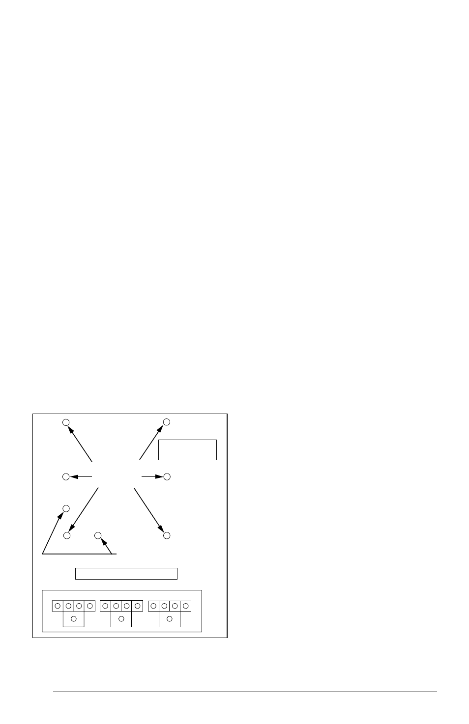
Circuit Breaker
Mounting Panel
Holes (Qty. 6)
Contactor Mounting Holes (Qty. 2)
Also See
Figure 9, pg. 18
Also See Figure 10, pg. 18
Figure 2. Control Mounting Location