Electrical wiring, Pre-electrical checklist, Line voltage – Reznor Q6SE Unit Installation Manual User Manual
Page 8: Rooftop, Horizontal to downflow conversion, Condensate drain, Warning
8
• Units require horizontal roof curb and return air kit for
horizontal installations.
• Ductwork should be attached directly to flanges on
panels supplied in horizontal duct conversion kits.
Rooftop
Rooftop installations must be located according to local
building codes or ordinances and these requirements:
• The roof must be capable of handling the weight of the
unit. For unit weights, see
. Reinforce
the roof if necessary.
• The appropriate accessory roof curb (
) must be
installed prior to unit installation. The roof curb must be
square and level to ensure proper condensate drainage.
Please follow all instructions provided with the kit.
• Secure roof curb or frame to roof using acceptable
mechanical methods per local codes.
notE:
Make sure
the two supports beneath the unit have been removed.
Roof
Curb
Figure 4. Roof top Installation
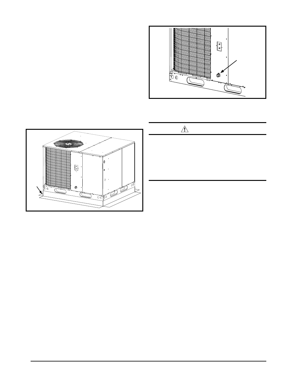
Figure 5. condensate Drain location
ElEctRIcAl WIRInG
WARnInG:
to avoid risk of electrical shock, personal injury,
or death, disconnect all electrical power to the unit
before performing any maintenance or service.
the unit may have more than one electrical supply.
label all wires prior to disconnection when
servicing the unit. Wiring errors can cause
improper and dangerous operation
• Electrical connections must be in compliance with
all applicable local codes and ordinances, and with
the current revision of the National Electric Code
(ANSI/NFPA 70).
• For Canadian installations the electrical connections
and grounding shall comply with the current Canadian
Electrical Code (CSA C22.1 and/or local codes).
Pre-Electrical checklist:
√ Verify that the voltage, frequency, and phase of the
supply source match the specifications on the unit rating
plate.
√ Verify that the service provided by the utility is sufficient
to handle the additional load imposed by this equipment.
refer to the unit wiring label for proper high and low
voltage wiring.
√ Verify factory wiring is in accordance with the unit wiring
diagram. See
. Inspect for loose
connections.
line Voltage
• A wiring diagram is located on the inside cover of the
units electrical box. The installer should become familiar
with the wiring diagram before making any electrical
connections to the outdoor unit.
•
An electrical disconnect must be located within sight
of and readily accessible to the unit. This switch shall
be capable of electrically de-energizing the unit.
• Line voltage to the unit should be supplied from a
dedicated branch circuit containing the correct fuse
or circuit breaker for the unit. Incoming field wiring
Condensate
Drain
Horizontal to Downflow conversion
The unit is shipped ready for horizontal duct connections.
If down flow ducts are required, the unit must be converted
following the steps below for the supply and return ducts.
1. Locate the duct cap inside the duct openings and remove
the screw holding it in place.
2. Lift the cap out of the unit. (
Hint: The cap can be pushed
up from the bottom by reaching through the fork slot).
3. Cover the horizontal duct opening with the horizontal
duct cap. The insulation will be on the indoor side.
4. Fasten the cover with screws to seal.
condensate Drain
Condensate is removed from the unit through the 3/4”
female pipe fitting located on the front side of the unit.
Install a 2 inch condensate trap in the drain line of the
same size and prime with water. See
.
When connecting rigid drain line, hold the female fitting
with a wrench to prevent twisting.
Do not over tighten!
Refer to local codes and restrictions for proper condensate
disposal requirements.