Figure 8. wiring diagram for 208/230v units, Wiring dia gram – Reznor Q6SE Unit Installation Manual User Manual
Page 15
15
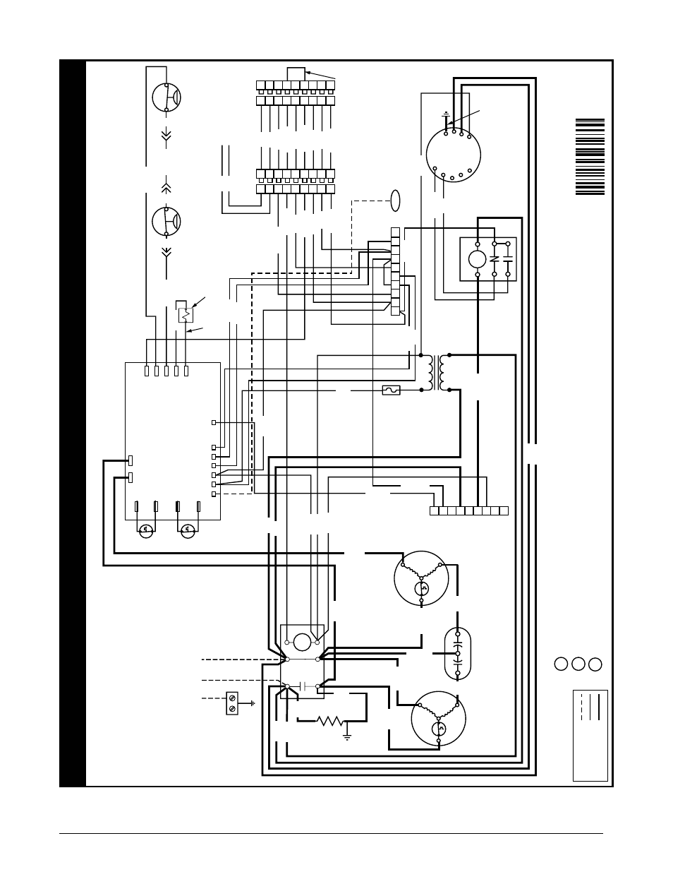
Figure 8. Wiring Diagram for 208/230V Units
1
2
3
4
5
6
7
8
9
G
C
A1
W1
R
Y2
E
O
Y1
W2
L1
L2
T1
T2
C
R
S
R
C
S
T2
T1
N
G
L
C
T3
T4
T5
TO
208/230
VA
C
PO
WER SUPPL
Y
9
8
1
7
6
5
4
3
2
9
8
1
7
6
5
4
3
2
9
8
1
7
6
5
4
3
2
9
8
1
7
6
5
4
3
2
COMPRESSOR
COMPRESSOR
DU
AL CAP
A
CIT
OR
HEA
TER
PLUG
OUTDOO
R
FAN M
OTO
R
DEFROS
T
SENSOR
ECONOMIZER
PLUG
ECONOMIZE
R
PLUG
TO
DISCHARGE
AIR SENSOR
3 AMP
FUSE
BLO
WE
R
RELA
Y
BL
OW
ER
M
OTO
R
BLA
CK
YELLO
W
RED
YE
YE
YE
CONT
AC
TO
R
F
H
C
24V
TRANSFORMER
240V
208V
COM
1
5
2
6
3
4
BLUE
ORANGE
FIELD
WIRIN
G
LEGEND
:
LO
W
VO
LT
AG
E
HIGH
VO
LT
AG
E
CCH
BLA
CK
BLACK
AMBIENT
SENSOR
M
PRESS
SW
RE
V
VA
LV
E
AMBIENT
AMBG
CO
IL
G
C
OIL
L
DEMAND
DEFROST
BO
ARD
R
CY
O
W2-IN
W2-OUT
C
OND
FA
N
BLA
CK
BLA
CK
REVERSING
VA
LVE SOLENOID
24VDC OUTPUT
TO
A COM
PA
TIBLE
THERMOS
TA
T
SEE II FOR DET
AILS
BLACK
208/230
Volt
Con
ver
tible
Pa
ck
ag
ed Heat Pump
Single Phase 60Hz
NO
TES:
1.
Disconnect all po
wer bef
ore servicing.
2.
For suppl
y connections use copper conductor
s onl
y.
3.
Not suitable on systems that e
xceed 150V to gr
ound.
4.
If an
y of the original wire as supplied with the furnace
m
ust be replaced,
it m
ust be replaced with wiring
material ha
ving a temperature rating of at least 105°C.
5.
For suppl
y wire ampacities o
ver
current pr
otection,
see
unit rating plate
.
1.
Couper le courant
av
ant de faire letretien.
2.
Emplo
yez uniquement des conducteur
s en cuivre
.
3.
Ne con
vient pas aux installations de plus de 150
V
a la terre
.
10064970
11/14
NO
TE:
See Installation
Instruc
tions f
or wirin
g,
application,
an
d
Inf
ormation concerning
accessor
y Heat Kits an
d
other options
.
WIRING DIA
GRAM
DEFR
OST BO
ARD OPERA
TION:
Heat Pump operates in heating mode until the combination of outdoor ambient and outdoor coil temperatures initiate
a defrost cycl
e.
The outdoor coil temperature must be at or belo
w 32°F bef
ore the defrost cycle begins
.
There must be a minimum of 20 minutes between defrost cycles
. After this tim
e,
temperature conditions must call
fo
r
defrost continuously
fo
r 4 1/2 minutes bef
ore a defrost cycle is initiated.
The defrost cycle ends when the outdoor temperature reaches 32°F or the defrost ter
minate time of 13 minutes 39
seconds is reached.
1
2
3
RED
RE
D
WHIT
E
YELLO
W
BLUE
YELLO
W
BLA
CK
GRA
Y
GREEN
GREEN
ORANGE
GREEN
BLA
CK
GRA
Y
YELLO
W
BLUE
YELLO
W
RED
RED
HIGH
PRESSUR
E
SWITC
H
LO
W PRESSURE
SWITC
H
GN
WITH
YE STRIPE
BLA
CK
ORANGE
YELLO
W
RED
RED
BROW
N
BR
OW
N
ORANGE
WHIT
E
WHIT
E
WHIT
E
YELLO
W
BLUE
YELLOW
BLA
CK
BLA
CK
BLA
CK
BLA
CK
RED
RED
BLA
CK
WHIT
E
RED
RED
YELLO
W
GRA
Y
YELLO
W
YELLO
W
ORANGE