Horizontal to downflow conversion, Removal of internal filter rack, Installing filters in the filter rack – Reznor P8SE Unit Installation Manual User Manual
Page 6: Removing filters from filter rack, Condensate drain
6
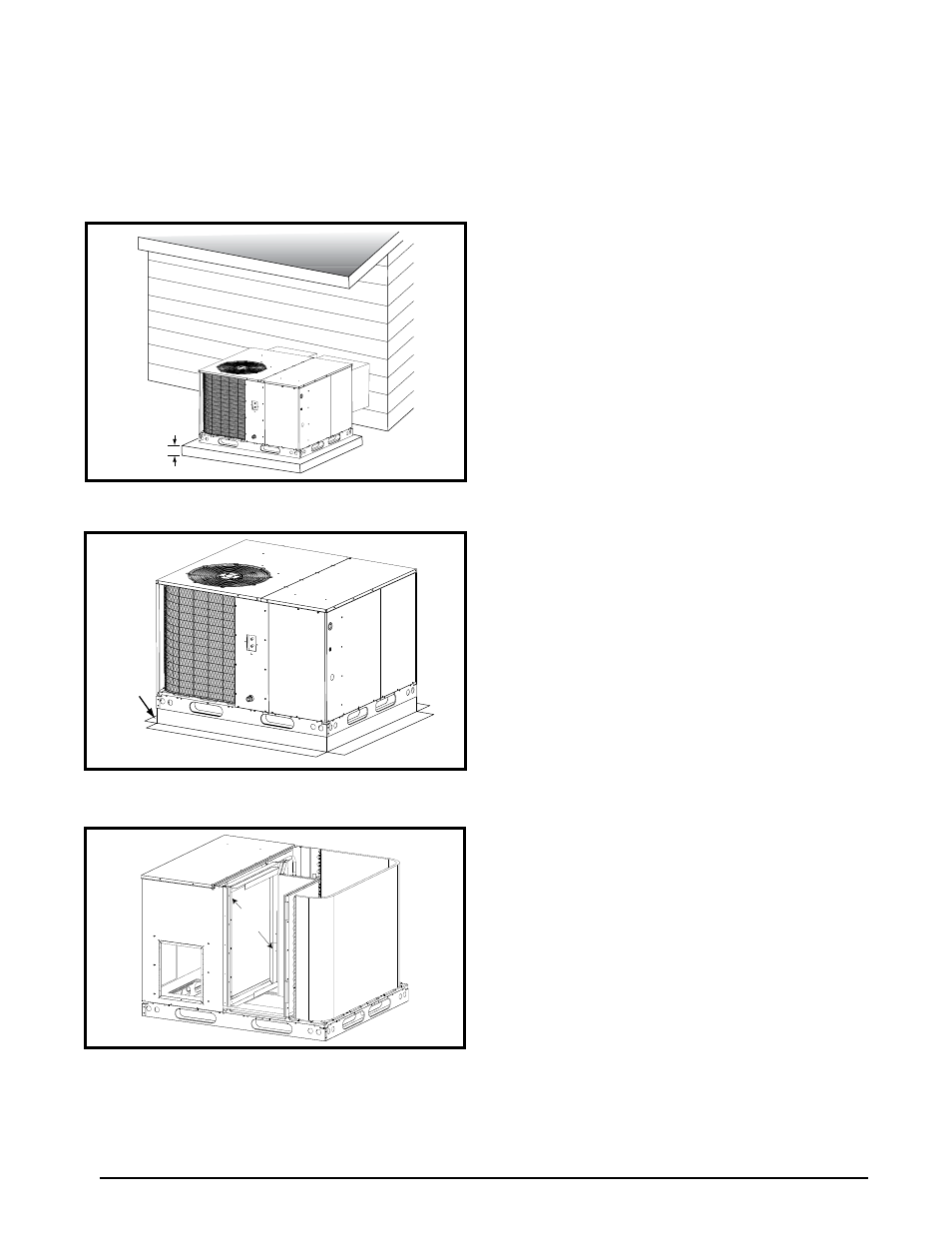
• The appropriate accessory roof curb (Figure 4) must be
installed prior to unit installation. The roof curb must be
square and level to ensure proper condensate drainage.
Please follow all instructions provided with the kit.
• Secure roof curb or frame to roof using acceptable
mechanical methods per local codes.
note:
Make sure
the two supports beneath the unit have been removed.
Roof
Curb
Figure 3. roof top installation
2”
Figure 2. ground level installation
Horizontal to downflow conversion
The unit is shipped ready for horizontal duct connections.
If down flow ducts are required, the unit must be converted
following the steps below for the supply and return ducts.
1. Locate the duct cap inside the duct openings and
remove the screw holding it in place.
2 Lift the cap out of the unit. (
Hint: The cap can be pushed
up from the bottom by reaching through the fork slot).
3. Cover the horizontal duct opening with the horizontal
duct cap. The insulation will be on the indoor side.
4. Fasten the cover with screws to seal.
removal of internal Filter rack
(3 Phase Only)
1. Remove the return air panel from the unit.
2. Remove the height adjustment screw from the inside
of the rack.
3. Remove (1) screw securing the assembly to the coil
located on the left leg of the rack.
note: The assembly
can now be easily collapsed and removed from the unit.
See
for filter rack securing screw locations.
installing Filters in the Filter rack
(3 Phase Only)
1. Remove access panel screws from return air panel.
(
Hint: Loosen the unit’s top panel screws near the
top edge of the access panel. The access panel was
designed to be captured underneath the top panel.)
2. Slide the first filter between both guide channels of filter
rack and allow the filter to drop easily into place.
3. Verify the bottom of the filter is within the channels of
the rack.
4. Slide the 2nd filter between both guide channels of filter
rack.
5. Verify the bottom of the filter is within the channels of
the rack.
6. Replace access cover by sliding the top edge of panel
under the lip of the unit’s top panel. Secure access
panel by replacing the screws.
removing Filters from Filter rack
(3 Phase Only)
1. Remove access panel screws from return air panel.
(
Hint: Loosen the unit’s top panel screws near the
top edge of the access panel. The access panel was
designed to be captured underneath the top panel.)
2. Remove upper filter by gently pulling filter through the
access panel opening.
3. Remove lower filter by lifting media to top of filter rack.
Remove in the same manner as described in step 2.
4. Install new filter in the filter rack as described in the
previous section.
condensate drain
Condensate is removed from the unit through the 3/4”
female pipe fitting located on the front side of the unit.
Install a 2 inch condensate trap in the drain line of the
same size and prime with water. When connecting rigid
drain line, hold the female fitting with a wrench to prevent
twisting.
do not over tighten! Refer to local codes and
restrictions for proper condensate disposal requirements.
Securing
Screws
Figure 4. internal Filter rack location