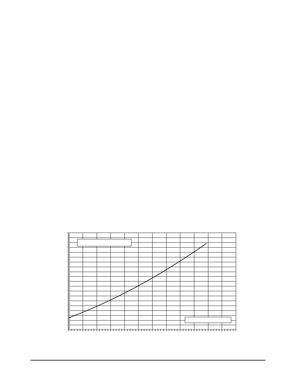
Charging the unit in ac mode, Charging charts & application notes, Figure 6. charging chart for 3 ton units – Reznor P8SE Unit Installation Manual User Manual
Page 12
12
• A low-pressure switch is factory-installed and located
in the suction line internal to the outdoor unit. The
switch is designed to protect the compressor from a
loss of charge. Under normal conditions, the switch is
closed. If the suction pressure falls below 5 psig, then
the switch will open and de-energize the outdoor unit.
The switch will close again once the suction pressure
increases above 20 psig. Please note that the switch
interrupts the thermostat inputs to the unit. When the
switch opens and then closes, there will be a 5 minute
short cycling delay before the outdoor unit will energize.
• To achieve rated capacity and efficiency the compressor
must be exposed to refrigerant for at least 24 hours prior
to running and then must be run for a minimum of 12
hours.
charging the unit in ac mode
At outdoor temperatures above 65° F
1. With the system operating at steady-state, measure
the liquid refrigerant pressure (in psig) at the outdoor
unit service valve.
2. Measure the liquid refrigerant temperature (in
Fahrenheit) at the service valve.
3. Determine the required liquid refrigerant pressure
from
,
.
• If the pressure measured in Step 1 is greater than
the required liquid refrigerant pressure determined
in Step 3, then there is too much charge in the
system. Remove refrigerant and repeat Steps 1
through 3 until the system is correctly charged.
• If the pressure measured in Step 1 is less than the
required liquid refrigerant pressure determined in
Step 3, there is too little charge in the system. Add
refrigerant and repeat Steps 1 through 3 until the
system is correctly charged.
charging charts & application notes
• This equipment’s cooling system contains refrigerant
under high pressure. Always use safe and environmen-
tally sound methods when handling refrigerant handling
or servicing the unit. Review the factory literature and
safety warnings prior to servicing.
• When repairing system leaks, always use a nitrogen
(inert) gas to protect the refrigerant system and pressure
check the repair before re-charging. Always replace
the filter-dryers when performing any repair to the
refrigeration system with one capable of acid removal.
After completing the repairs, evacuate the system to
350 - 500 microns and weigh in the refrigerant to the
amount specified on the unit rating label.
• The refrigerant charging charts,
,
, or
are applicable only to matched assemblies
of NORDYNE equipment and listed airflows for the
indoor coil. NOTE: Before using these charts, make
sure the unit is in a stable operating mode. As shown
in the charts, the ideal system sub-cooling can vary
over the range of operation. Reference the charts to
determine the ideal amount of sub-cooling for a given
liquid pressure. Units charged to other values will not
perform at the rated unit efficiency (EER).
• For systems that are operating with more than a 5%
deviation, inspect the unit for the proper voltage and
phase balance and the refrigeration system for leaks.
• Units that are operating at less then 95% of the nominal
voltage or with a 2% phase imbalance may see a more
significant deviation than the amount stated above.
• DO NOT use the charts in systems that have a fan cycling
under low-ambient control. Refer to the low-ambient kit
instructions for more information (If applicable).
75
80
85
90
95
100
105
110
115
120
125
130
Liquid Pressure (psig
)
Liquid Temperature (° F)
P8SE-X36 Charging Chart - Cooling
200
220
240
260
280
300
320
340
360
380
400
420
440
460
480
500
520
540
560
580
600
135
Remove refrigerant if above curve
Add refrigerant if below curve
Figure 6. charging chart for 3 ton units