Wiring dia gram – Reznor PDF2SF Unit Installation Manual User Manual
Page 31
31
FIELD
WIRING
LEGEND:
LO
W
VO
LT
AG
E
HIGH
VO
LT
AG
E
1.
Couper le courant
av
ant de faire letretien.
2.
Emplo
yez uniquement des conducteur
s en cuivre
.
3.
Ne co
nv
ient pas aux installations de plus de 150
V a la terre
.
208/230
V
olt
.
z
H
0
6 /
e
s
a
h
P
el
g
ni
S
m
et
s
y
S
d
e
g
a
k
c
a
P
g
nil
o
o
C
d
n
a
g
ni
t
a
e
H l
e
u
F l
a
u
D
NO
TES:
1.
Disconnect po
wer bef
ore servicing.
2.
For suppl
y connections use copper conducto
rs
onl
y.
3.
Not suitable on systems that e
xceed 150V to gr
ound.
4.
If an
y of the original wire as supplied with the furnace
mu
st be replaced
,
it m
ust
be replaced with wiring material ha
ving a temperature rating of at least 105°C.
5.
For suppl
y wire ampacities and o
ver
current pr
otection,
see unit rating plat
e.
6.
Ensure that wires fr
om the blo
wer remain connected to the boa
rd
thermostat terminals after
making the field thermostat connections.
7.
A heat pump thermostat with f
ossil fuel bac
k-up heat capability is REQUIRED f
or this system.
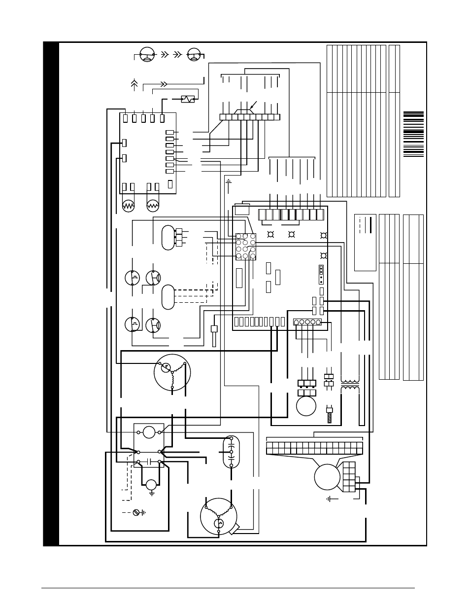
WIRING DIA
GRAM
SYSTEM ST
A
TUS - IGNITION
Po
wer On (Nor
mal Operation)
High Limit Circuit Open
Pressure Switch Open with Inducer On
Pressure Switch Closed with Inducer Off
F
ailed Ignition (5 attemps) - Control in 1 Hour Loc
ko
ut
208-230
V
olt P
olar
ity Issue
Excess High limit tr
ips (5) within one call f
or heat
Excess pressure s
witch cycles (5) within one call f
or heat
Excess flame dropouts (5) within one call f
or heat
Not Used
Flame present with gas
va
lv
e Off
LED ST
A
TUS (RED)
ON
1 Flash
2 Flashes
3 Flashes
4 Flashes
5 Flashes
6 Flashes
7 Flashes
8 Flashes
9 Flashes
10 Flashes
SYSTEM ST
A
TUS - 2nd ST
A
GE HE
AT
DEMAND
No demand f
or 2nd stage heat
2nd stage heat demand (Nor
mal operation)
2nd stage heat demand, high pressure
sw
itch not closed
LED ST
A
TUS (GREEN)
OFF
ON
Flashing
SYSTEM ST
A
TUS - CFM
NO
T USED
LED ST
A
TUS (YELLO
W)
OFF
SYSTEM ST
A
TUS - HI/LO DEHUMIDIFY (Cooling Mode on
ly
)
F
acto
ry
jumper wire
“R
”
to
“DEHUM”
in place or
“Close on F
all”
humidistat (Lo
w humidity) - Closed
Humidistat open (High Humidity) Lo
w Speed Bl
ow
er call
LED ST
A
TUS (GREEN)
ON
OFF
DEFR
OST BO
ARD OPERA
TION:
-- Heat Pump operates in heating mode until the combination of outdoor ambient
and outdoor coil temperatures initiate a defrost cycle. The outdoor coil
temperature must be at or below 32˚F before the defrost cycle begins.
-- There must be a minimum of 20 minutes between defrost cycle
s.
After this
time, temperature conditions must call for defrost continuously for 4 1/2
minutes before a defrost cycle is initiated.
-- The defrost cycle ends when either the outdoor coil temperature sensor reaches
the defrost terminate set point, or 13 minutes, 39 seconds of compressor run time
has elasped with the control in the defrost mode. (See installation instructions for
available terminate temperatures and their specific jumper location)
7111840
(Replaces 711137A)
11/11
GAS
VA
LV
E
624787
GAS
VA
LV
E
624652
HI
LO
GAS
VA
LV
E
C
BR
OW
N
YELLO
W
YELLO
W
BR
OW
N
TEST
LR
CY
O
W2
IN
W2
OUT
COND
FA
N
AMBIENT
AMBG
COILG
COIL
DEMAND
DEFR
OST CONT
RO
L
BO
ARD
M
PRESS
SW
REV
VA
LV
E
2
1
3
6
5
4
7
8
9
12
11
10
W1
W2
C
R
G
Y
Y2
0
DEHUM
P2
1
5
(CFM)
YEL
GREEN
HI/LO
DEHUMIDIFY
(HIGH HE
AT
DEMAND)
GREEN
(S
TA
TUS)
RED
1
2
3
1
2
3
INDUCER
MO
TO
R
FLAME R
OLL-OUT
SWITCH
HIGH
TEMP LIMIT
SWITCH
FLAME SENSOR
LPS
DU
AL CAP
A
CIT
OR
TERM.
STRIP
REV
. VA
LV
E
SOLENOID
5
4321
5
4321
VA
RIABLE
SPEED
BLO
WER
MO
TO
R
1
2
3
4
5
6
7
8
9
10
11
12
13
14
15
16
1
2
3
4
5
6
7
8
9
10
11
12
13
14
15
16
R
S
C
C
HF
TO
208/230
VA
C
PO
WER SUPPL
Y
IGNIT
OR
CONT
AC
TO
R
COMPRESSOR
L1
L2
T1
T2
COIL
SENSOR
AMBIENT
SENSOR
G
C
L
W1
R
Y2
E
O
Y1
W2
TRANSFORMER
240V
208V
24V
COM
BR
OW
N
BR
OW
N
BLA
CK
BLA
CK
CCH
IF
EQUIPPED
HPS
YELLO
W
YELLO
W
NEUTRALS
HUM
LINE
XMFR
CO
NT
EA
C
CO
OL
PA
RK1
PA
RK2
HI-HEA
T
LO
-HEA
T
P6
16-
PIN
OUTDOOR
F
AN MO
TO
R
BLA
CK
YELLO
W
YELLO
W
5A FUSE
R
S
C
BLUE
ORANGE
BLUE
BLUE
AU
TO
HEA
T ST
AG
E
10 5 NONE
IGNITION / BLO
WER
CONTR
OL BO
ARD
COOL
A B C D
HEA
T
A B C D
ADJUST
NORM
(+)
(-)
TEST
LO
W
PRESSURE
SWITCH
HIGH
PRESSURE
SWITCH
HI
LO
GAS
VA
LV
E
C
2
1
3
BLUE
BLUE
BL
AC
K
RED
BR
OW
N
BR
OW
N
BLACK
RED
GREEN
BLA
CK
VIOLET
ORANGE
WHITE
YELLO
W/BL
AC
K
BLA
CK/WHITE
BLA
CK
BLA
CK
BLA
CK
GREEN
YELLO
W
YELLOW
YELLO
W
YELLO
W
BROW
N
BR
OW
N
GREEN
YELLO
W
ORANGE
BLUE
RED
BLA
CK
WHITE
WHITE
BROW
N
YELLOW
ORANGE
RED
BLAC
K
BLAC
K
WHITE
BR
OW
N
GREEN
YELLO
W
ORANGE
BLUE
RED
BL
AC
K
RED
RED
WHITE
RED
WHITE
WHITE
WHITE
RED
BLAC
K
YELLOW
YELLO
W
RED
BLA
CK
Figure 14. Two-Stage Cool, Two Stage Heat (Heat Pump)
Two-Stage gas Heating (2 & 5 Ton Only)