Wiring diagrams, Dehum – Reznor PDF2SF Unit Installation Manual User Manual
Page 30
30
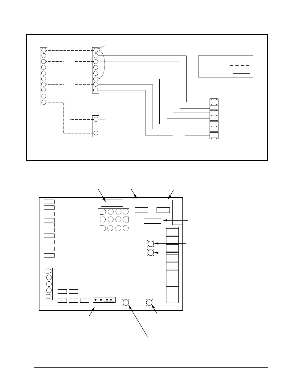
WIRING DIAGRAMS
Figure 13A. Thermostat Connection for Two Stage Heating / Two Stage Cooling Configuration
Legend
Field Wiring
Factory Wiring:
TERMINAL
STRIP
TYPICAL HEAT PUMP
THERMOSTAT
R
Y1
G
Y2
C
W2
W1
R
Y1
G
Y2
C
W2
W1
RED
YELLOW
GREEN
BLACK
BLUE
WHITE
BROWN
R
C
Y
G
W1
Y2
W2
BLUE
BROWN
S2 Heat Pump (Heat / Cool)
S2 Gas Heat
24VAC Com
S1 Gas Heat
Fan
S1 Heat Pump (Heat / Cool)
24VAC
Reversing Valve
(See Note 1)
NOTES:
1. Reversing valve energized in cooling mode of operation. Refer to the thermostat manual for detailed installation and programming instructions.
2. For use with standard heat pump thermostats with defrost control board fault monitoring only.
E
E
Emergency Heat
O
L
O
L
Fault Monitoring
(See Note 2)
IGNITION / BLOWER
CONTROL BOARD
DEFROST
BOARD
W1
W2
C
R
G
Y
Y2
0
DEHUM
P2
1
5
HUM
LINE
XMFR
CONT
EAC
COOL
PARK1
PARK2
HI-HEAT
LO-HEAT
NEUTRALS
AUTO
HEAT STAGE
10 5 NONE
HOT SURFACE IGNITION
VARIABLE SPEED BLOWER
CONTROL BOARD
COOL
A B C D
HEAT
A B C D
ADJUST
NORM
(+)
(-)
TEST
Low Voltage
Control Circuit
5 Amp Fuse
Heating Speed
Selector (Table 11)
Cooling Speed
Selector (Table 10)
CFM Adjustment Selector
Cooling Speed Only(Table 10)
LED (Yellow) - Not Used
LED (Green) - Dehumidification
(Cooling Mode Only) See Page 13
& Troubleshooting Page 23
LED (Red) - Ignition
(See Operating Sequence
& Troubleshooting)
LED (Green) - High Heat Demand
(See Troubleshooting)
Automatic Heat Staging
(Used with Single Stage
Heating Thermostat)
Figure 13b. Two-Stage, Hot Surface Ignition & blower Control board