Warning, Caution, Manifold pressure adjustment – Reznor PDF2SF Unit Installation Manual User Manual
Page 20: Verifying burner operation, Refrigerant charging
20
NOTE: The over-temperature limit control should turn
off the gas valve within approximately four minutes
(exact time depends on the efficiency of the close-off
when blocking the return air). The circulating air and
combustion blowers should continue to run when the
over-temperature limit control switch opens.
4. Remove the close-off plate immediately after the over-
temperature limit control opens. If the unit operates
for more than four minutes with no return air, set the
thermostat below room temperature, shut off power to
the unit, and replace the over-temperature limit control.
Manifold Pressure Adjustment
The manifold pressure must be set to the appropriate
value for your installation. To adjust the manifold pressure:
1. Obtain the required manifold pressure setting. Use
Table 6 for natural gas or Table 7 for LP/propane gas.
NOTE: The values listed in the tables are based on sea
level values. At higher altitudes, the heating value of
gas is lower than the sea level heating value.
2. Remove the regulator cap. Turn the high fire
adjusting screw clockwise to increase the pressure or
counterclockwise to reduce the pressure. See Figure
10 (page 25) for adjusting screw locations.
3. Replace the regulator cap after adjustments are
complete.
Verifying burner Operation
WARNING:
Uninsulated live components are exposed when
louvered control access panel is removed.
1. Remove the louvered control access panel and verify
there is power to the unit.
2. Set thermostat above room temperature and observe
the ignition sequence. NOTE: The burner flame should
carry over immediately between all burners without
lifting off, curling, or floating. The flames should be blue,
without yellow tips. Make sure the flame is drawn into
the center of the heat exchanger tube. In a properly
adjusted burner assembly, the flame bends down and
to the right at the end of the heat exchanger tube. The
end of the flame will be out of sight around the bend.
3. After validating flame characteristics, set the thermostat
below room temperature and verify the burner flame
extinguishes completely.
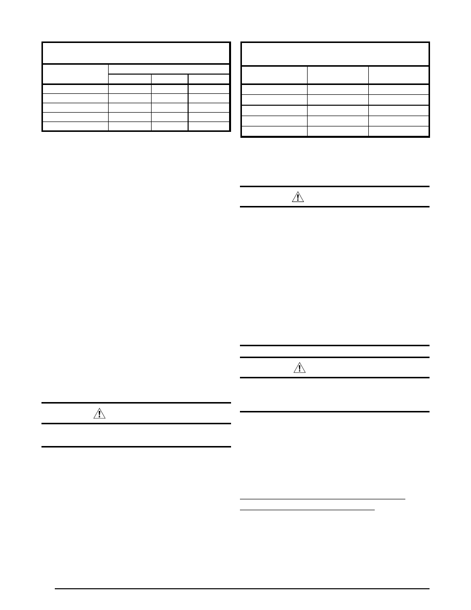
Table 6. Manifold Pressure (in W.C.) for Natural gas
Manifold Pressure (in W.C.) for
Natural gas Installations
Altitude above
sea level
Heating Value btu/cu. ft.
800 to 899
900 to 999 1,000 to 1,100
zero to 1,999 FT
3.5
3.5
3.5
2,000 to 4,999 FT
3.5
3.5
3.5
5,000 to 5,999 FT
3.5
3.5
3.0
6,000 to 7,999 FT
3.5
3.2
2.8
8,000 to 10,000 FT
3.0
2.8
2.5
Table 7. Manifold Pressure (in W.C.) for LP gas
Manifold Pressure (in W.C.) and Orifice Sizes
for LP/Propane gas Installations
Altitude above
sea level
Manifold
Pressure
Orifice
Size
zero to 1,999 FT
10.0
55
2,000 to 4,999 FT
8.5
55
5,000 to 5,999 FT
10.0
56
6,000 to 7,999 FT
9.0
56
8,000 to 10,000 FT
8.5
56
NOTE: Manifold pressure based on sea level LP heating value
of 2,500 Btu/cu. ft.
3
Refrigerant Charging
WARNING:
These units are shipped fully charged with
R-410A refrigerant and ready for installation.
When a system is installed according to these
instructions, no refrigerant charging is required.
If repairs make it necessary for evacuation and
charging, it should only be done by qualified,
trained personnel thoroughly familiar with this
equipment. Some local codes require licensed
installation/service personnel to service this
type of equipment. Under no circumstances
should the owner attempt to install and/or
service this equipment. Failure to comply with
this warning could result in property damage,
personal injury, or death.
CAUTION:
This unit uses R-410A refrigerant. DO NOT use
any other refrigerant in this unit. Use of another
refrigerant will damage the unit.
The system refrigerant charge can be checked and
adjusted through the service ports provided at the front
panel. Use only gauge lines which have a Schrader
depression device present to actuate the valve. Refrigerant
charging must be done by qualified personnel familiar with
safe and environmentally responsible refrigerant handling
procedures. Refer to the application notes and charging
charts on pages 37 - 39
Charging an R-410A unit in AC mode at
outdoor temperatures above 65F.
1. With the system operating at steady-state, measure the
liquid refrigerant pressure in psig at the service valve.
2. Measure the liquid refrigerant temperature in Fahrenheit
at the outlet of the condensor coil.
3. For the temperature measured, determine the required
liquid refrigerant pressure from the appropriate charging
charts in Figures 18 - 21 (pages 38 & 39).