Caution, Troubleshooting, Cleaning of burners – Reznor PDF2SF Unit Installation Manual User Manual
Page 24
24
TROUBLESHOOTING
If the unit does not operate in the cooling mode, check
the following:
• The thermostat is operating properly
• Electrical power to the unit is turned on
• The filters are not dirty
• The service doors are in place
• The 5 amp fuse is operational
If the unit does not operate in the heating mode, check
the following:
• The thermostat is operating properly
• Electrical power to the unit is turned on
• The filters are not dirty
• The gas is turned on and the manual shut-off valve
is open
• The service doors are in place
• The flame roll-out control is closed
• The diagnostic codes listed in Table 7 or on the
wiring diagrams (Figures 14 - 17, pages 31 - 34).
• The 5 amp fuse is operational
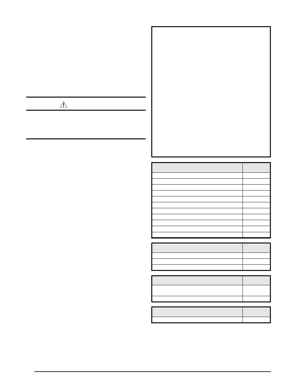
Table 8. Ignition / blower Control Diagnostic Codes
SYSTEM STATUS - IGNITION
LED STATUS
(RED)
Power On (Normal Operation)
ON
High Limit Circuit Open
1 Flash
Pressure Switch Open with Inducer On
2 Flashes
Pressure Switch Closed with Inducer Off
3 Flashes
Failed Ignition (5 attempts) - Control in 1 Hour Lockout
4 Flashes
208-230 Volt Polarity Issue
5 Flashes
Excess High limit trips (5) within one call for heat
6 Flashes
Excess pressure switch cycles (5) within one call for heat
7 Flashes
Excess flame dropouts (5) within one call for heat
8 Flashes
Not Used
9 Flashes
Flame present with gas valve Off
10 Flashes
SYSTEM STATUS - 2nd STAGE HEAT DEMAND
LED STATUS
(gREEN)
No demand for 2nd stage heat
OFF
2nd stage heat demand (Normal operation)
ON
2nd stage heat demand, high pressure switch not closed
Flashing
SYSTEM STATUS - HI/LO DEHUMIDIFY
(Cooling Mode only)
LED STATUS
(gREEN)
Factory jumper wire “R” to “DEHUM” in place or “Close
on Fall” humidistat (Low humidity) - Closed
ON
Humidistat open (High Humidity) Low Speed Blower call
OFF
SYSTEM STATUS - CFM
LED STATUS
(YELLOW)
NOT USED
OFF
Cleaning of burners
If the burners require cleaning, follow the steps below.
1. Shut off the gas supply to the unit either at the meter
or at a manual valve in the supply piping.
2. Turn off all power to the unit and set the thermostat to
the lowest temperature setting.
3. Remove the louvered control access panel from the
unit.
4. Turn the gas control knob to the OFF position. See
Figure 12 (page 29) for gas valve shut off instructions.
5. Disconnect the wires from the gas valve, ignitor, and
flame sensor.
CAUTION:
To prevent damage to the unit or internal
components, it is recommended that two
wrenches be used when loosening or tightening
nuts. Do not over tighten!
6. Using two wrenches, separate the ground-joint union
in the gas supply piping at the unit.
7. Remove the piping between the gas valve and the
ground-joint union (if applicable).
8. Remove all screws securing the burner assembly to
the furnace.
9. Carefully remove the burner assembly from the furnace.
DO NOT DAMAGE THE IGNITER WHILE REMOVING
THE BURNER ASSEMBLY.
10. Inspect the burners for accumulated dust or debris.
If necessary carefully clean them with a soft wire
brush and a vacuum cleaner. DO NOT DAMAGE THE
IGNITER WHILE CLEANING THE BURNER.
11. Replace all the parts in reverse order from which they
were removed.
12. Follow the lighting instructions found on the lower unit
door to return the unit to operation.
13. Verify proper operation after servicing.