Water connections – Reznor RBL Option - Installation - Evaporative Cooling Option User Manual
Page 8
Form I-OPT-EC, Page 8
AquaSaver Timed Metering Control System
- If the cooling module is equipped
with a timed metering system, connect a 1/2" water line to the fitting on the side of the
cooling module.
Due to various water pressures and installation conditions, the water supply line may
bang abruptly when the solenoid valve in the AquaSaver system closes. This banging
Evaporative
Cooling
Module
Float valve inlet water connection
(1/4 compression) or inlet water
connection to solenoid valve
for metering system (1/2 male fitting)
Overflow fitting -
3/4 garden hose
thread tapped with
1/2 female NPT
Drain fitting - 3/4
garden hose thread
tapped with
1/2 female NPT
2-way solenoid valve
(normally open)
3-way
solenoid
valve
To drain
Pressure regulator
(10 psi max)
Service valve
Roof
= Field-installed water piping
A (N.O.)
B (N.C.)
Water
inlet
= Field supplied
FIGURE 11 - Water
Connections including
Optional Drain and Fill
Kit
Instructions for Installing Optional Fill & Drain Kit
2. Run field-supplied black wire from the electrical
compartment (terminal on the wiring diagram) of the
evaporative cooling module and connect to the black
wire on both the 3-way and the 2-way valve.
3. Run field-supplied white wire from the electrical
compartment (terminal on the wiring diagram) of the
evaporative cooling module and connect to the white
wire on both the 3-way and the 2-way valve.
NOTE: Follow instructions included in the valve pack-
ages for attaching valves to the water line only. The re-
mainder of the installation instructions with the valves do
not apply to this type of application.
Water Line Connections (See illustration.)
:
Supply (3-Way Valve) Connections - Connect the water
supply line to "B" (normally closed). Connect the water drain
line to "A" (normally open). Connect the middle outlet to
supply the water to the cooling module reservoir.
Drain (2-Way Valve) Connections - Connect the drain pipe
from the reservoir to "A". Connect the outlet side to "B" and
connect into drain lines from the cooling reservoir and the
supply valve.
Electrical Connections (requires black and white 14-gauge
wire) - Refer to Wiring Diagram provided with the fur-
nace:
WARNING: Risk of electrical shock. Disconnect the power.
1. Refer to the wiring diagram for terminal connections.
(NOTE: If kit is not ordered with the system, connections
will not be shown on the diagram. Terminal connections
are specific to each system. Contact the factory for
terminal connections. Be prepared to provide all model
information. )
8. Water
Connections
WARNINGS: Water reservoir (outdoor systems) must be drained
and pump motor turned off when outside temperature falls below
32°F. Pump must never be operated without water in the reservoir.
Supply and Drain Water Connections
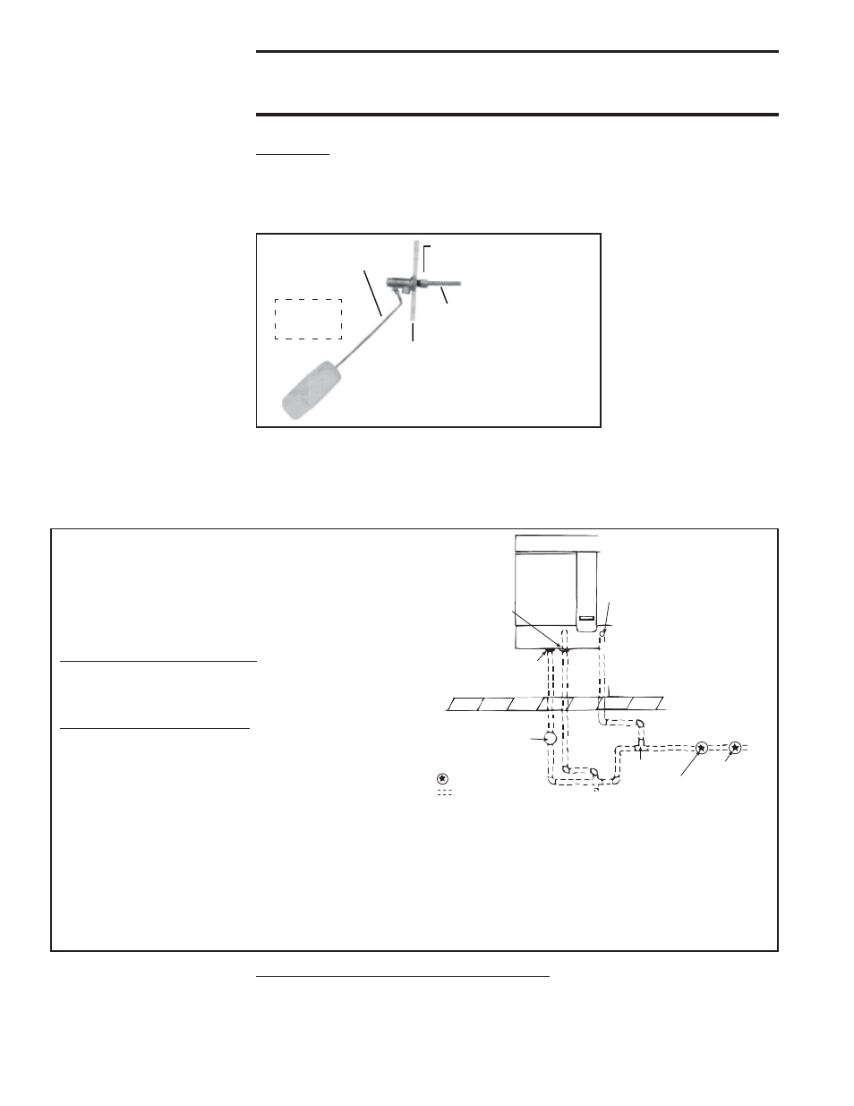
Float Valve
(FIGURE 10) - In a module with pump and float controls, a float valve
maintains the appropriate water level in the reservoir.
Use a field-supplied 1/4" diameter tubing with a compression nut and tubing ferrule to
connect the fresh water supply to the inlet of the float valve. Place nut and ferrule over
tubing and insert tubing into the float valve stem. Tighten nut securely.
FIGURE 10 - Connect
Fresh Water Supply to
Inlet of Float Valve
Compression Nut and
Tubing Ferrule
Use 1/4” tubing for
fresh water supply.
Simulates
Side
Panel
Float Valve Rod
Inside
Cabinet
An optional automatic fill and drain kit will automatically release supply water to the
cooling module when a call for cooling is made and will drain all water from the
reservoir when the cooling switch is deactivated or a cooling thermostat is satisfied. If
installing an optional fill and drain kit, see FIGURE 11 and follow the instructions that
apply. Consult the wiring diagram for electrical connections.
- ADFH Option - Installation - Evaporative Cooling Option ADF Option - Installation - Evaporative Cooling Option PGBL Option - Installation - Evaporative Cooling Option SSCBL Option - Installation - Evaporative Cooling Option RPBL Option - Installation - Evaporative Cooling Option RGBL Option - Installation - Evaporative Cooling Option