Installing opt- ional moisture elimination pads – Reznor RBL Option - Installation - Evaporative Cooling Option User Manual
Page 5
Mfg No. 160202, Page 5
5. Installing Opt-
ional Moisture
Elimination
Pads
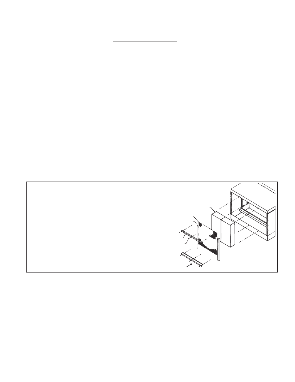
Media Pads
Screen
Screen Retainer
Top Pad Retainer
Screw
Bottom Pad
Retainer
FIGURE 5 - Removal (and Replacement) of Media Pads
Option ASA1 moisture elimination pads are shipped separately for field installa-
tion. Follow these installation instructions. If this option is not being installed, con-
tinue to Paragraph 6.
Media pads must be removed to install the moisture elimination pads (See FIG-
URE 5
). FIGURE 6 illustrates installation of the moisture elimination pads.
Remove Media Pads
1)
Remove the three sheetmetal screws that hold the top
pad retainer.
2)
Release the top pad retainer from the cooling module.
3)
Remove the three sheetmetal screws that hold the
bottom pad retainer. Release the bottom pad retainer
from the cooling module.
4)
Disengage the screen retainers from the sides of the
media.
5)
Disengage the inlet screen from the media pads and
remove from the cooling module.
6)
Slide all media pads horizontally away from cooling
module until clear of bottom reservoir pan.
instructions on pages 5 and 6 for removal and replacement of media pads. If
optional moisture elimination pads are being included, media pads will have to
be removed to complete the installation.
18)
If there are no duct extensions on the transition duct, reach inside the cooling
module and fasten the cooler to the back of the cabinet and panel as shown in
STEP #18
. There are no holes in the cabinet end panel, so six #10x1/2" long
self-drilling sheetmetal screws must be used. The screws are provided in the
duct kit and are recognizable by their drill bit type cutter and slotted head.
19)
If there are duct extensions on the transition duct, reach inside the cooling
module and fasten the duct extensions to the back of the cabinet end panel as
shown in STEP #19. There are no holes in the end panel, so four #10x1/2"
long self-drilling sheetmetal screws must be used. The screws are provided in
the duct kit and are recognizable by their drill bit type cutter and slotted head.
20)
Attach bottom of duct assembly, by using seven #10 x 1/2" long self-drilling
screws, to the cabinet end panel as shown in STEP #20.
21)
The evaporative cooling module should now be installed. Be certain all
screws are in place. Seal all corners of the transition duct assembly with a
waterproof silicone sealant to prevent moisture from entering the cabinet.
Install Moisture
Elimination Pads
(See FIGURE 6,
page 6.)
1)
Prepare module by attaching two catch pad clamps to one side of the cooler’s
front legs. Screw through the legs into the clamp with four of the #10 x 1/2"
long sheetmetal screws provided.
2)
Prepare catch pads by assembling them together. Use three of the #10 x 1/2"
long sheetmetal screws provided.
3)
Guide the catch pad assembly through the inlet of the cooling module and
place the bottom of the lower pad into the catch pad mounting trough. The
screen part of the catch pad assembly should always be facing the attached air
mover. Slip the catch pad assembly into the two slots located in the catch pad
clamps installed in Step (1).
4)
With the pads in place, complete the assembly by sliding one of the two
remaining clamps over the middle seam where the assembled catch pads meet.
Slip the other clamp over the top catch pad frame and fasten both clamps to
the cooling module leg using sheetmetal screws provided.
- ADFH Option - Installation - Evaporative Cooling Option ADF Option - Installation - Evaporative Cooling Option PGBL Option - Installation - Evaporative Cooling Option SSCBL Option - Installation - Evaporative Cooling Option RPBL Option - Installation - Evaporative Cooling Option RGBL Option - Installation - Evaporative Cooling Option