Reznor RBL Option - Installation - Evaporative Cooling Option User Manual
Page 3
Mfg No. 160202, Page 3
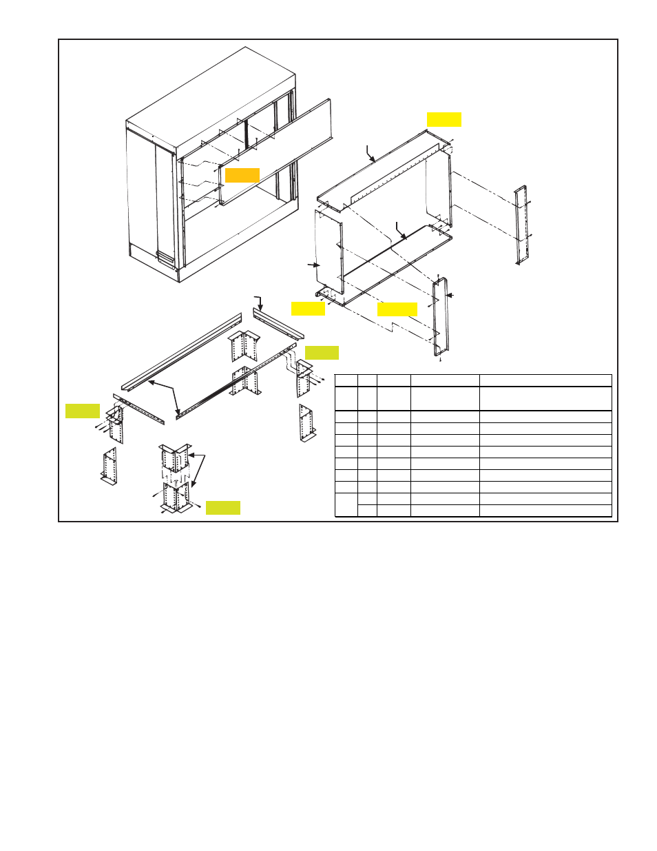
Cooling Module
Transition Duct
(connects cooling
module to makeup
air system)
Cooling Module
Base (must
be field
assembled)
ITEM 1
ITEM 5
ITEM 7 (2)
ITEM 6
ITEM 8
ITEM 9 (2)
Used on BL
Sizes 500, 600,
700, & 1050 only.
Not required on
other Models
and Sizes.
ITEM 2
(2)
ITEM 3 (2)
ITEM 4
(4 sets)
Step 2
Step 4
Step 5
Step 7
Step 8
Step 9
Step 11
Item Qty
P/N
Description
Where Used:
1
1
Evaporative
Cooling Module
Factory-assembled for field
attachment to a makeup air system
2
2
107235 Support Ends
Base Assembly
3
2
107227 Support Sides
Base Assembly
4
8
107236 Leg Halves
Base Assembly
5
1
107228 Front Top Cover Cooling Module
6
1
107229 Duct Top
Transition Duct
7
2
107231 Duct Side
Transition Duct
8
1
107230 Duct Bottom
Transition Duct
2
107233 Duct Extensions “BL” Models 500 and 600
2
107234 Duct Extensions “BL” Models 700 and 1050
9
FIGURE 2 - Parts List and Illustration for
Assembling Base and Transition Duct for
Optional Evaporative Cooling Module
6)
Carefully lift the evaporative cooling module (ITEM 1) from both ends and place it on the
completed base assembly. Be certain that the cooling module is level and all base assem-
bly bolts are secure.
7)
Attach front top cover (ITEM 5) to cooling module, as shown in STEP #7 using 13 of the
# 10 x 1/2" long sheetmetal screws. There will be three screws per side and seven screws
across the top.
Attaching
Cover and
Assembling
Transition
Duct
(FIGURE 2,
STEPS 7-11)
8)
Attach transition duct sides (ITEM 7) to duct top (ITEM 6) using eight, #10 x 1/2"
long sheetmetal screws. As shown in STEP #8, there will be four screws per side.
9)
Fasten the duct bottom (ITEM 8) to the transition duct sub-assembly begun above
by following STEP #9, using eight of the #10 x 1/2" long sheetmetal screws
provided. Again, there will be four per side.
10)
If the packaged heating system is a “BL” 500, 600, 700 or 1050 size, the duct
extensions (ITEM 9) must also be installed on the transition duct. If the packaged
heater is a “BL” 400, 800, or 1200 size, an RBL, or an ADF/ADFH, skip STEP
11
and continue with STEP 12.
11)
There are two sizes of the duct extensions. One is used to fit the “BL” 500 or 600
size heaters; one fits the 700 and 1050 size heaters. To fasten the duct extension
(ITEM 9) to the transition duct assembly, use 14 #10 x 1/2" long metal screws as
shown in STEP #11. Five screws will be used on each side of the extension and
one up through the bottom of the extension.
- ADFH Option - Installation - Evaporative Cooling Option ADF Option - Installation - Evaporative Cooling Option PGBL Option - Installation - Evaporative Cooling Option SSCBL Option - Installation - Evaporative Cooling Option RPBL Option - Installation - Evaporative Cooling Option RGBL Option - Installation - Evaporative Cooling Option