Electrical connections, Warning: disconnect power to the unit – Reznor RBL Option - Installation - Evaporative Cooling Option User Manual
Page 7
Mfg No. 160202, Page 7
7. Electrical
Connections
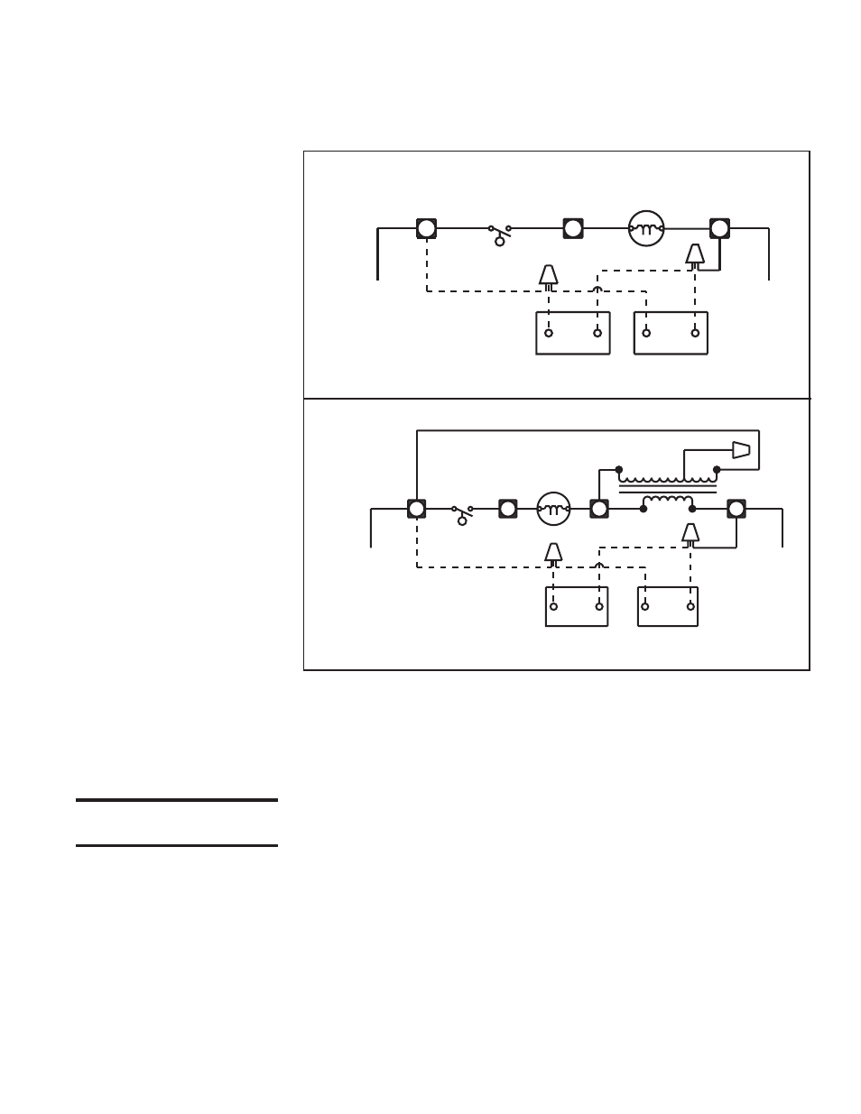
Line voltage wiring must be field installed between the blower junction box and the
evaporative cooling module junction box. The tubing-encased wires are factory-
connected in the cooling module junction box.
NOTE:
Models ADF/ADFH have only 115V optional evaporative cooling module
pumps. A transformer is included on the unit.
FIGURE 9A - Diagram of
Evaporative Cooling
Module Factory-Installed
Wiring -- “BL” Models
with 115/230/1/60 or 230/
460/575/3/60 (Heater
Options AK3, 6, 7 or 8) and
Models ADF/ADFH 700/
1200 (see Note above)
FIGURE 9B - Diagram of
Evaporative Cooling
Module Factory-Installed
Wiring -- Systems with 208/
1-3/60 (Heater Option AK2
or AK5)
V
W
PUMP MOTOR
LINE VOLT
SWITCH
FLOAT
W
BK
H
BK
J
Y
N.O. TWO WAY
DRAIN VALVE
FILL VALVE
THREE WAY
OPTIONAL
OPTIONAL
Y
115-230/1/60
COOLING CIRCUIT
111145 REV #4
EVAPORATIVE COOLING MODULE
BK
N.O. TWO WAY
DRAIN VALVE
FILL VALVE
THREE WAY
OPTIONAL
OPTIONAL
208/1/60
COOLING CIRCUIT
111452 REV #4
BK
PUMP MOTOR
230 VOLT
FLOAT
SWITCH
V
Y
W
H
W
BK
BUCK-BOOST
40 VA. TRANSFORMER
BK
I
Y
J
R
BK
BL
BR
Y
EVAPORATIVE COOLING MODULE
Y
Instructions for
“Internal Field-
Required Wiring
From Cooling Module
to System Cabinet
WARNING: Disconnect
power to the unit.
NOTE:
The two snap strain relief bushings are shipped in the bottom pan of the
cooling module.
1. Remove the compartment door panels and electrical compartment cover.
Remove the service panel in line with the hole in the cooling module.
2. Drill a 7/8" hole in the cabinet end panel in line with the hole in the cooling
module junction box.
3. Pull the tubing-encased wires through the hole in the blower cabinet. Place the
strain relief bushings around the tubing and insert the bushing into the hole
(Bushing must be used to prevent water from leaking into the cabinet). Route
the wires across the cabinet bottom. If there are any filters, run the wires
through the slot in the bottom filter rack. If there are inlet dampers, be careful
that the wires do not interfere with the damper controls. Run the wires up to
the electrical compartment, remove a plug from one of the bottom entrance
hole, and push the tubing-encased wires into the electrical compartment. Place
the other strain relief bushing around the tubing and insert the bushing into the
hole in the electrical compartment.
4. Follow the wiring diagram included with the heater to properly connect the
wires to the terminal blocks. If there is excess tubing and/or wiring, trim
before making connections.
5. Before unit is operated, replace all door panels and fasten all latches.
- ADFH Option - Installation - Evaporative Cooling Option ADF Option - Installation - Evaporative Cooling Option PGBL Option - Installation - Evaporative Cooling Option SSCBL Option - Installation - Evaporative Cooling Option RPBL Option - Installation - Evaporative Cooling Option RGBL Option - Installation - Evaporative Cooling Option