Reznor CAUA Option - Installation - Filter Cabinet User Manual
Page 3
Form I-CAUA-FC, P/N166162R2, Page 3
Installation
Preparation -
Options CW 4, 5, 6,
7, 11, and 12
FIRST, verify that the kit received is the appropriate one for the installation. Check
the heater size and the CFM. (NOTE: Some side and rear packages are identical.)
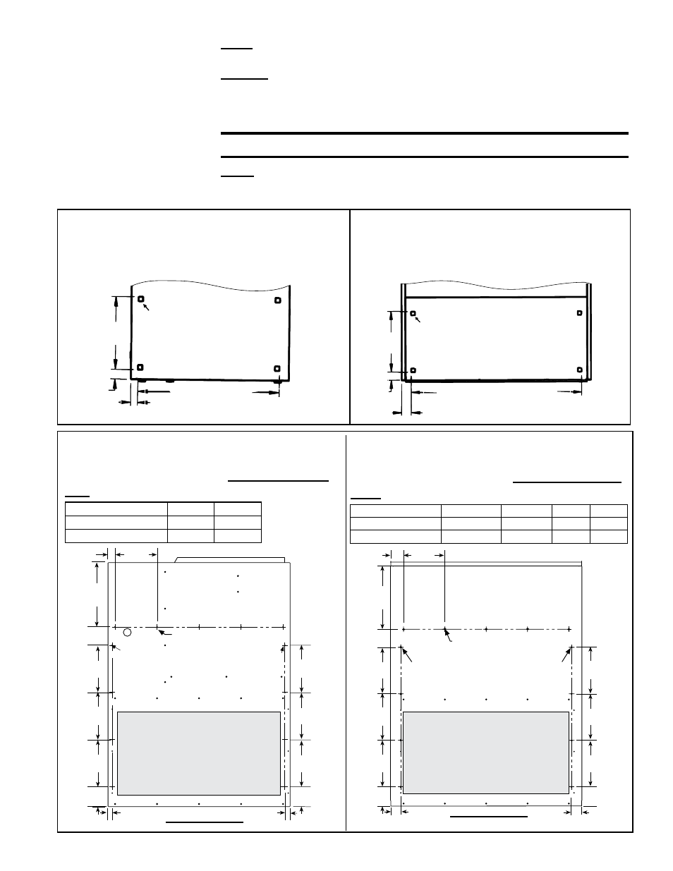
SECOND, where the filter cabinet is going to be attached to the heater, find four
embosses in the metal panel. For
side attachment, see FIGURE 1A; for rear attach-
ment,
see FIGURE 1B. These embosses are corner indicators for the inlet air open-
ing. Using tin snips or aviation shears, carefully cut straight lines between the corner
marks until the opening is created.
CAUTION: The cut edges of the metal cabinet will be sharp.
THIRD, refer to the illustrations in FIGURES 2A and 2B. Select the appropriate illus-
tration and drill the required 1/8" holes in the side or rear of the heater cabinet where
the filter cabinet is being installed.
FIGURE 1B - Heater Inlet Air Opening
Dimensions (inches and mm) for installing
Rear Filter Cabinet, Option CW7, CW12, or
CW11
FIGURE 1A - Heater Inlet Air Opening
Dimensions (inches and mm) for installing
Side Filter Cabinet, Option CW4, CW5, or
CW6
Corner indicators for cutting
inlet air opening
2-1/2
(64mm)
2-1/8
(54mm)
16
(406mm)
Heater Cabinet Rear Panel
Sizes 150, 200 - 33 (838mm)
Sizes 250, 300, 350, 400 - 45 (1143mm)
FIGURE 2A - Reference Drawing for Drilling
1/8" Holes in the SIDE of a Model CAUA
Heater when Installing an Option CW 4, 5,
or 6 Return Air Filter Cabinet
FIGURE 2B - Reference Drawing for Drilling
1/8" Holes in the REAR of a Model CAUA
Heater when Installing an Option CW 7, 12,
or 11 Return Air Filter Cabinet
SIDE - Sizes
A
E
150, 200, 250, 300 8 (203) 5 (127)
350, 400
9 (229) 6 (152)
REAR - Sizes
B
C
D
E
150, 200, 250, 300 2-15/32 (63)
3 (76)
8 (203) 5 holes
350, 400
1-29/32 (48) 2-1/2 (64) 9 (229) 6 holes
9
(229)
9
(229)
3-3/4
(95)
9
(229)
3-3/4
(95)
9
(229)
9
(229)
9
(229)
A Typ
12-1/4
(311)
1-11/32
(34)
13/16
(21)
13/16
(21)
Heater Cabinet Side
1/8 (3.2) dia.
E = Number of holes
1/8 (3.2) dia.
4 holes on
each side
1/8 (3.2) dia.
4 holes on
each side
Cutout Inlet Opening
Heater Cabinet Rear
(measure B & C from the the corner of the heater)
Cutout Inlet Opening
C
D Typ
12-1/4
(311)
9
(229)
9
(229)
9
(229)
3-3/4
(95)
B
B
3-3/4
(95)
9
(229)
9
(229)
9
(229)
1/8 (3.2) dia.
E = Number of holes
1/8 (3.2) dia.
4 holes on
each side
1/8 (3.2) dia.
4 holes on
each side
16
(406mm)
2-1/8
(54mm)
1-1/2
(38mm)
Corner indicators for
cutting inlet air opening
Sizes 150, 200, 250,
300 - 31 (787mm)
Sizes 350 and 400 - 44 (1118mm)
Heater Cabinet Side Panel