Reznor CAUA Option - Installation - Filter Cabinet User Manual
Installation instructions, Description/ application, Form i-caua-fc (version .2)
Form I-CAUA-FC, P/N166162R2, Page 1
Form I-CAUA-FC (Version .2)
Obsoletes I-CAUA-FC (Version .1)
Installation Instructions
Applies to:
Optional Return Air Filter
Cabinet for Model CAUA
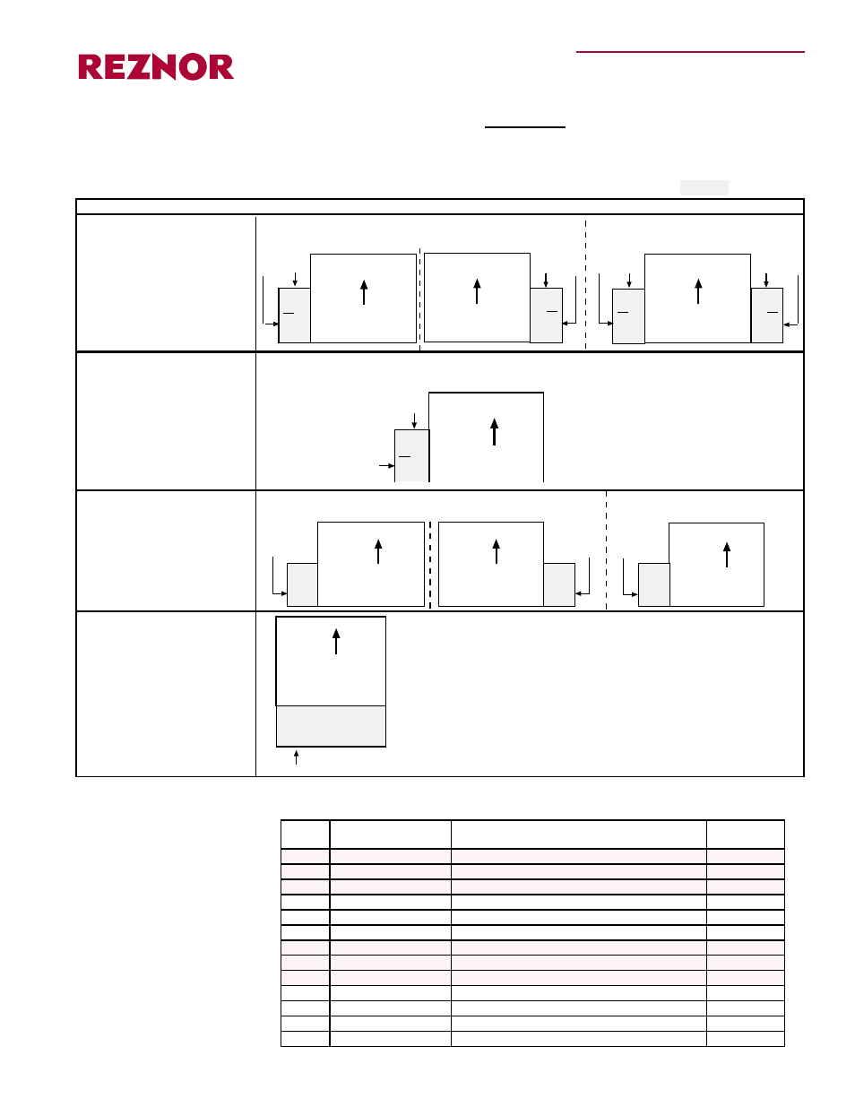
Description/
Application
Optional return air filter
cabinets for Model CAUA
packaged heating systems
are available in a variety
of configurations (see
illustrations above).
Table of Contents by Option and Configuration
(Option CW return air filter cabinet is shaded.)
Filter Cabinet ............... Pages
CAUA
Front View
Top
or
Rear
Inlet
Top
or
Rear
Inlet
Entering
return air
Entering
return air
Entering
return air
CAUA
Front View
CAUA
Front View
Entering
return air
Airflow
Airflow
Airflow
Top
or
Rear
Inlet
Top
or
Rear
Inlet
Rear
Inlet
only
Rear
Inlet
only
CAUA
Left Side View
Front of heater
Entering
return air
Entering
return air
Entering
return air
Rear
Inlet
only
CAUA
Front View
CAUA
Front View
Airflow
Airflow
Airflow
Model CAUA
(any view; all sizes)
Return air enters
from bottom
Bottom Return
Air Filter Cabinet
Airflow
CAUA
Left Side View
Top
or
Rear
Inlet
Front of Heater
Entering
return air
Airflow
Entering
return air
Installation instructions for all types are in this form. Select and apply the information
for the option that matches your installation.
Options CW 4, 5, 6
Description/Application .. 1-2
Components...................... 2
Preparation .................... 3-4
Installation Instructions
with Rear Inlet .......... 4-6
with Top Inlet ............ 6-8
Options CW 7, 12, 11
Description/Application ...1-2
Components ...................... 2
Preparation .....................3-4
Installation Instructions
with Rear Inlet ..........4-6
with Top Inlet ............6-8
Options CW 8, 9, 10
Description/Application ..1-2
Components ...................... 8
Preparation ....................... 9
Installation Instructions
with Rear Inlet ........ 9-11
Options CW 13, 14, 15, 16
Description/Application .. 1-2
Components.....................11
Preparation ......................11
Installation Instructions ... 12
CW 4, 5, 6 attached to Either Side of
Model CAUA - all sizes
CW 4, 5, 6 attached to Both Sides
of Model CAUA 250 or 300
CW 7, 12, 11 attached to Rear of Model CAUA - all sizes
CW 8, 9, 10 attached to Either Side of
Model CAUA 150 or 200
CW 8, 9, 10 attached to Rear of
Model CAUA 150 or 200
CW13, 14, 15, 16 acts as a base
allowing return air to enter vertically
from under a Model CAUA heater.
Option Factory or Field
Filter Type
Applies to
CAUA Sizes
CW4
Field assembled
2" Pleated
All
CW5
Field assembled
2" Permanent
All
CW6
Field assembled
2" Field-supplied (pleated or permanent only)
All
CW7
Field assembled
2" Pleated
All
CW12
Field assembled
2" Permanent
All
CW11
Field assembled
2" Field-supplied (pleated or permanent only)
All
CW8
Field assembled
2" Pleated
150 and 200
CW9
Field assembled
2" Permanent
150 and 200
CW10
Field assembled
2" Field-supplied (pleated or permanent only)
150 and 200
CW13
Factory assembled
2" Disposable
All
CW14
Factory assembled
2" Pleated
All
CW15
Factory assembled
2" Permanent
All
CW16
Factory assembled
2" Field-supplied (pleated or permanent only)
All
®