Reznor CAUA Option - Installation - Filter Cabinet User Manual
Page 2
Form I-CAUA-FC, Page 2
Components - Options CW 4, 5, 6, 7, 11, and 12
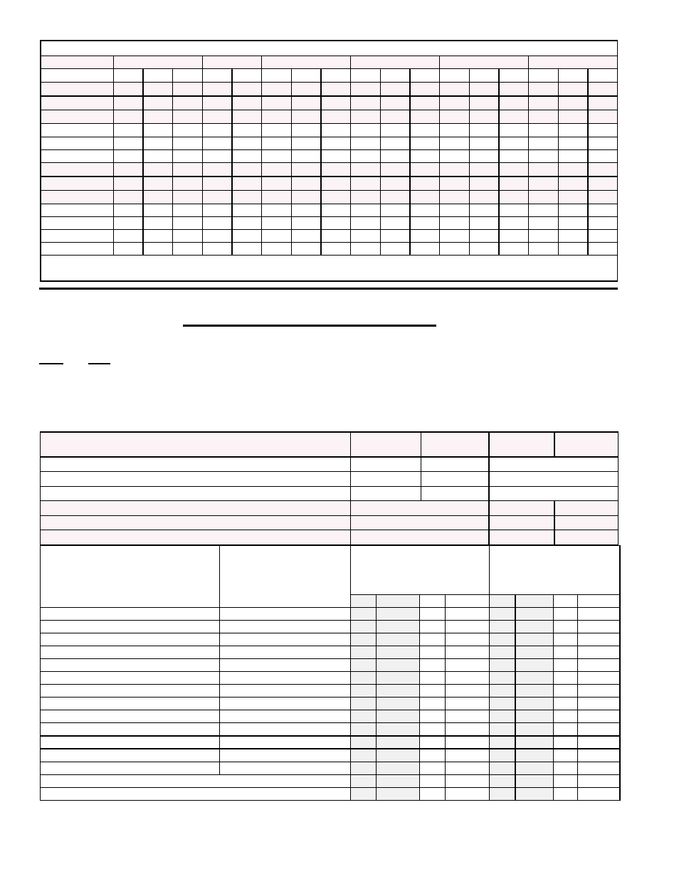
Rear and side filter cabinets, Options CW 4, 5, 6, 7, 11 and 12, are shipped separately for field assembly and installa-
tion. (The cabinets are assembled as they are installed.) The table below lists the Package P/N's and the components
in each package by package P/N and by Model Size.
Before beginning installation, verify that all parts are available at the job site.
LARGE RETURN AIR FILTER CABINETS FOR ATTACHING TO REAR OR SIDE
OF MODEL CAUA - OPTIONS CW 4, 5, 6, 7, 11, AND 12
Optional Filter Cabinet Applications (X = available;
■
= not available or not for use at the CFM)
Model CAUA
150
200
250
300
350
400
CFM
1800 2400 3000 2400 3000 3000 4000 5000 3000 4000 5000 4300 5000 6000 4300 5000 6000
Option CW4
X
X
X
X
X
X
■
■*
X
■
■*
X
X
■
X
X
■
Option CW5
X
X
X
X
X
X
X
■*
X
X
■*
X
X
X
X
X
X
Option CW6
X
X
X
X
X
X
X
■*
X
X
■*
X
X
X
X
X
X
Option CW7
X
X
X
X
X
X
X
X
X
X
X
X
X
■
X
X
■
Option CW12
X
X
X
X
X
X
X
X
X
X
X
X
X
X
X
X
X
Option CW11
X
X
X
X
X
X
X
X
X
X
X
X
X
X
X
X
X
Option CW8
X
X
■
X
■
■
■
■
■
■
■
■
■
■
■
■
■
Option CW9
X
X
X
X
X
■
■
■
■
■
■
■
■
■
■
■
■
Option CW10
X
X
X
X
X
■
■
■
■
■
■
■
■
■
■
■
■
Option CW13
X
X
X
X
X
X
X
X
X
X
X
X
X
X
X
X
X
Option CW14
X
X
X
X
X
X
X
X
X
X
X
X
X
X
X
X
X
Option CW15
X
X
X
X
X
X
X
X
X
X
X
X
X
X
X
X
X
Option CW16
X
X
X
X
X
X
X
X
X
X
X
X
X
X
X
X
X
*
For 5000 CFM on Sizes 250/300, either install a cabinet on the rear of the heater or two side cabinets (one on each side of the
heater).
Components by Option Package - CW 4, 5, and 6 attach to the side of the heater; CW 7, 12, and 11 attach to rear of heater.
For Model CAUA
150/200/
250/300
350/400
150/200
250/300/
350/400
Option CW4 (with 2" pleated filters) - Pkg P/N
166153
166156
Option CW5 (with 2" permanent filters) - Pkg P/N
166154
166157
Option CW6 (for field-supplied 2" filters) - Pkg P/N
166155
166158
Option CW7 (with 2" pleated filters) - Pkg P/N
166153
166156
Option CW12 (with 2" permanent filters) - Pkg P/N
166154
166157
Option CW11 (for field-supplied 2" filters) - Pkg P/N
166155
166158
Component Description
Component Usage by
Location of the Return Air
Inlet in the Filter Cabinet
Filter cabinet attaches
to side of heater with
horizontal (rear) or vertical
(top) inlet
Filter cabinet attaches
to rear of heater with
horizontal (rear) or vertical
(top) inlet
Qty
P/N
Qty
P/N
Qty
P/N
Qty
P/N
Bottom Panel
Vertical (Top) & Horizontal
1
160925
1
160926
1 160925 1
160926
Side Panel
Vertical (Top) & Horizontal
1
160634
1
160634
1 160634 1
160634
Rear or Top Inlet Panel (w/duct flange)
Vertical (Top) & Horizontal
1
160927
1
164520
1 160927 1
164520
Top Panel or Bottom Rear Panel
Vertical (Top) & Horizontal
1
160630
1
160631
1 160630 1
160631
Top Rear Panel
Vertical (Top) & Horizontal
1
160632
1
160633
1 160632 1
160633
Door Panel Assembly
Vertical (Top) & Horizontal
1
165033
1
165033
1 165033 1
165033
Door Channel
Vertical (Top) & Horizontal
2
160635
2
160635
2 160635 2
160635
Filter Support
Horizontal Inlet only
2
160636
2
165018
2 160636 2
165018
Filter Support Channel
Horizontal Inlet only
2
160923
2
160924
2 160923 2
160924
Filter Support
Vertical (Top) Inlet Only
2
164524
2
164525
2 164524 2
164525
Filter Channel Assembly
Vertical (Top) & Horizontal
1
165035
1
165036
1 165035 1
165036
Sheetmetal Screws #10-32 x 1/2" long
Vertical (Top) & Horizontal
54 113275 54 113275
54 113275 54 113275
Corner Braces
Vertical (Top) & Horizontal
2
166151
2
166151
2 166151 2
166151
2" Permanent Filters * in Options CW5 and CW12
4
104103
6
104103
4 104103 6
104103
2" Pleated Filters * in Options CW4 and CW7
4
104109
6
104109
4 104109 6
104109
*See page 6 for filter dimensions for cabinets installed with horizontal (rear) inlet air opening or page 8 for filter dimen-
sions for cabinets installed with vertical (top) inlet air opening.