Reznor CAUA Option - Installation - Filter Cabinet User Manual
Page 11
Form I-CAUA-FC, P/N166162R2, Page 11
STEP 6 Final Steps
Parts Required:
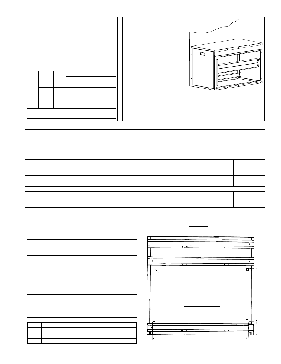
Door Assembly
Instructions:
Install the door on the
end of the filter cabinet.
Installation is complete.
Duct flange dimensions
for connecting ductwork are shown on page 9.
After heater installation is complete and return air ductwork
is connected, turn on the electric and the gas and check for
proper operation.
STEP 5 Install Filters
Parts Required:
Filters (either shipped with the option
package or field-supplied)
Instructions:
Slide the filters into the filter rack
channels.
BOTTOM RETURN AIR FILTER CABINET OPTIONS CW 13, 14, 15, AND 16
Components - Options CW 13, 14, 15, and 16
Bottom filter cabinets with bottom duct openings, Options CW 13, 14, 15, and 16 are shipped factory assembled. Pack-
age P/N by Option and Model Size are listed below.
Installation Preparation - Options CW 13, 14, 15, and 16
FIGURE 9 - Heater Inlet Air Opening Dimensions for installing Bottom Filter Cabinet,
Option CW13, CW14, CW15, or CW16
Sizes
150, 200
250, 300
350, 400
A
34" (864mm)
46" (1168mm)
46" (1168mm)
B
4-5/8" (117mm) 4-3/4" (121mm) 4-7/8" (124mm)
C
19" (483mm)
16" (406mm)
32" (813mm)
CAUTION: The cut edges of the metal
cabinet will be sharp.
Special instructions for bottom filter cabinet -
When cutting the opening in the bottom of the Model
CAUA, the unit will have to be tipped. Provide ade-
quate support for the unit during this process. If the
installation includes an optional cooling coil and/or a
discharge plenum, cut inlet air opening before adding
these accessories.
WARNING: When cutting the inlet air
opening in the bottom of a Model CAUA,
provide adequate support for the unit.
Sizes of Permanent or Pleated 2" Filters for
Options CW8, CW9, CW10
Size CFM FPM
2" Filters
Pleated
Permanent
150
1800
375 (2) 12 x 32 (4) 12 x 16
2400
500 (2) 12 x 32 (4) 12 x 16
*3000 625
--
(4) 12 x 16
200
2400
500 (2) 12 x 32 (4) 12 x 16
*3000 625
--
(4) 12 x 16
*Application requires 2" permanent filters; do
not use pleated filters.
Filter
Cabinet
Door
Assembly
Model CAUA Size
150 and 200
250 and 300
350 and 400
Option
CW13, Bottom filter cabinet with 2" disposable filters
195165
195166
195167
Option
CW14, Bottom filter cabinet with 2" pleated filters
195154
195155
195156
Option
CW15, Bottom filter cabinet with 2" permanent filters
195157
195158
195159
Option
CW16, Bottom filter cabinet with filter racks for field-supplied 2" filters
195160
195161
195162
Filter P/N's and sizes:
Filters in Option CW13,
16 x 16 x 2 disposable filters
(6) 104101
(8) 104101
(12) 104101
Filters in Option CW14,
16 x 16 x 2 pleated disposable filters
(6) 104109
(8) 104109
(12) 104109
Filters in Option CW15,
16 x 16 x 2 permanent aluminum filters
(6) 104103
(8) 104103
(12) 104103
BOTTOM VIEW
of CAUA Heater
Corner indicators for
cutting inlet air opening.
Front (Control Side) of Heater
C
A
B
2
(51mm)