Installation instructions (cont'd), Primary heater, Heater secondary – Reznor VR Option - Installation - Multiple Heater Control (Options CL31 and CL32) User Manual
Page 8
Form I-OPT-MH, P/N 102247 R7, Page 8
131127
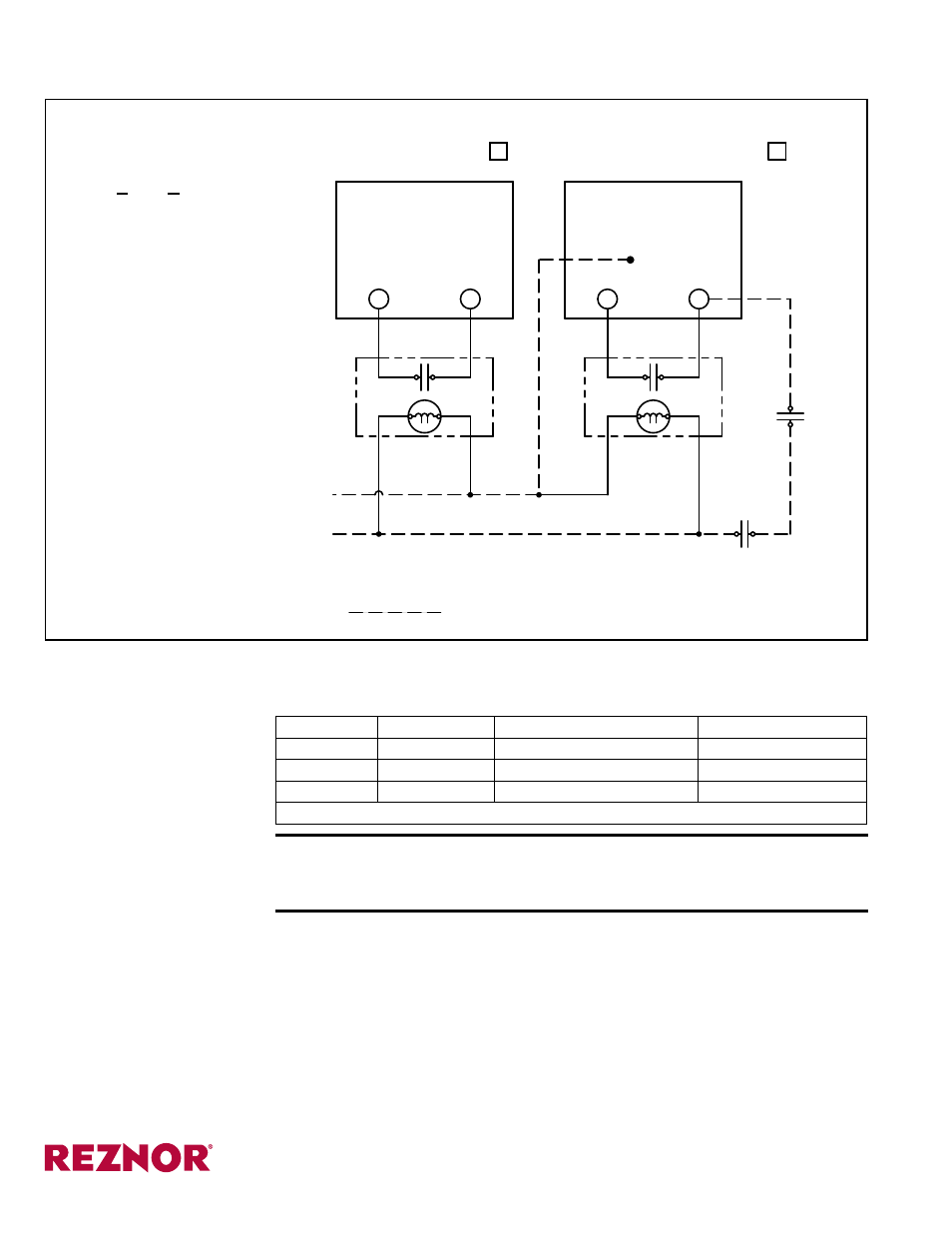
CHECK APPROPRIATE BOX:
PRIMARY HEATER
SECONDARY HEATER
REV #2
4
2
3
1
PRIMARY
HEATER
3
4
1
2
R
W1
W1
R
GRD STRIP
OR G67
ON G77
BR
BR
BR
BR
BR
BL
BL
BL
BL
R
R
R
CONTROL DEVICE
OR OTHER
THERMOSTAT
R
R
BL
BR
W
W
R
BL
BR
FIELD SUPPLIED WIRING
FIELD WIRING HAVING A MINIMUM TEMPERATURE RATING OF AT LEAST 105 DEGREES C.
SHALL BE USED. SUPPLY CIRCUIT WIRING SHALL HAVE A MINIMUM SIZE OF 18 AWG.
ADDITIONAL
SECONDAR
Y HEA
TERS
TO
TIME CLOCK
CONTACTS
OPTIONAL
DEVISE
CONTROL
OR OTHER
NOTE #1
NOTE #1: ON STANDING PILOTS MODELS, ATTACH TO BROWN WIRE ON GAS VALVE.
HEATER
SECONDARY
FIGURE 3C - Multiple
Heater Control Wiring
Diagram Label for
Models F and B,
P/N 131127
For future identification,
check appropriate box on
each wiring diagram label.
Installation
Instructions (cont'd)
www.ReznorHVAC.com
(800) 695-1901
©2014 Reznor, LLC. All rights reserved.
Trademark Note: Reznor
®
, T
CORE
2
®
, and V3
®
are registered in at least the United Stages.
0514 Form I-OPT-MH (Version D.2)
Do not exceed the control wire lengths shown in the table.
CAUTION: Be careful not to short thermostat leads to a metal
surface. Doing so will cause the transformer to fail, requiring it to
be replaced.
6. Turn on the electric power and the gas. Follow the lighting instructions to
operate the heater.
Check the control system for proper and safe operation.
Field Control Wiring (Length and Gauge)
Wire Type
Wire Gauge
Maximum Wire Length*
Maximum Distance
TEW
18
500 ft (152M)
250 ft (76M)
TEW
14
1300 ft (457M)
650 ft (198M)
TEW
12
2100 ft (640M)
1050 ft (320M)
*Wire length equals wire for circuit going plus wire for returning circuit.
5. Control Wiring (cont'd)
- B Option - Installation - Multiple Heater Control (Options CL31 and CL32) F Option - Installation - Multiple Heater Control (Options CL31 and CL32) UEAS Option - Installation - Multiple Heater Control (Options CL31 and CL32) UDBS Option - Installation - Multiple Heater Control (Options CL31 and CL32) UDBP Option - Installation - Multiple Heater Control (Options CL31 and CL32) UDAS Option - Installation - Multiple Heater Control (Options CL31 and CL32) UDAP Option - Installation - Multiple Heater Control (Options CL31 and CL32) LDAP Option - Installation - Multiple Heater Control (Options CL31 and CL32)