Reznor VR Option - Installation - Multiple Heater Control (Options CL31 and CL32) User Manual
Page 5
Form I-OPT-MH, P/N 102247 R7, Page 5
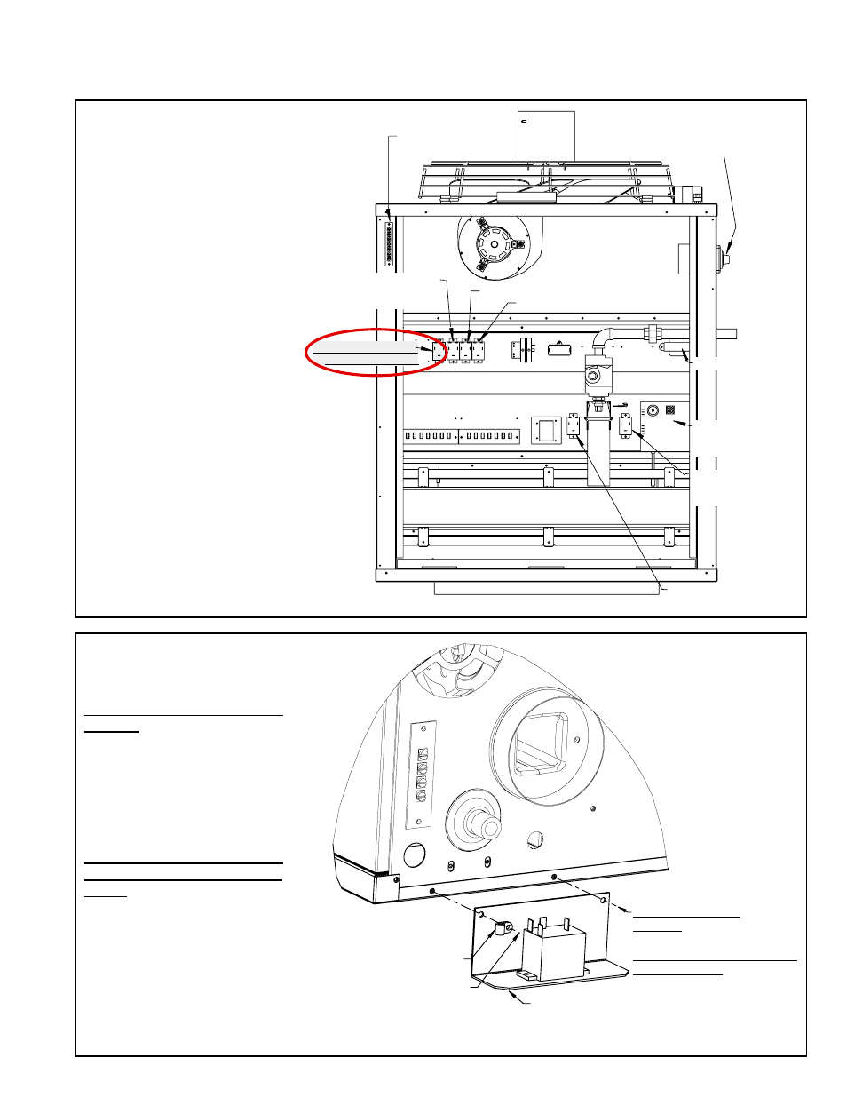
FIGURE 2A - Model LDAP
Remove the access panel from
the main heat section.
Locate the position on the
control panel for the new relay.
Attach the relay with the
screws provided in the kit.
3. Install a Relay or Relay Bracket Assembly on the “Primary” Unit and all
“Secondary” Units – Option CL31 and Option CL32. Select the appropriate
FIGURE (2A, 2B, 2C, or 2D) for the Model of Heater.
Disconnect
Switch
Transformer
DSI Control
(Circuit
Board)
Fan
Permissive
Relay
Heat Permissive Relay
(Models 800 and 1200)
Relay (primary and
secondary units)
24V Thermostat
Terminal Board
Burner Assembly
Vent Permissive
Relay (Models
800 and 1200)
Destrat (Fan Conrol) Relay
Remote Destrat (Fan Control) Relay
Model UD Sizes
30-125 use existing
cabinet screw.
Model UD Sizes 150-400
and all UEAS
use self-drilling
screw in the kit.
Relay
Bracket
Assembly
Cable Clamp
All model
sizes use
existing
screw.
FIGURE 2B - Models UDAP, UDAS,
UDBP, UDBS, UEAS
Model UD Sizes 30, 45, 60, 75,
100, 125 - On the rear of the
heater, position the bracket as
illustrated.
Remove the screws from the edge
of the cabinet bottom.
Re-insert the screws attaching the
relay bracket.
Model UD Sizes 150, 175, 200,
225, 250, 300, 350, 400 and all
UEAS - On the rear of the heater,
position the bracket as illustrated.
Remove the screw on the left from
the edge of the cabinet bottom.
Re-insert the screw attaching the
bracket.
Secure the other side of the
bracket with the self-drilling screw
in the kit.
- B Option - Installation - Multiple Heater Control (Options CL31 and CL32) F Option - Installation - Multiple Heater Control (Options CL31 and CL32) UEAS Option - Installation - Multiple Heater Control (Options CL31 and CL32) UDBS Option - Installation - Multiple Heater Control (Options CL31 and CL32) UDBP Option - Installation - Multiple Heater Control (Options CL31 and CL32) UDAS Option - Installation - Multiple Heater Control (Options CL31 and CL32) UDAP Option - Installation - Multiple Heater Control (Options CL31 and CL32) LDAP Option - Installation - Multiple Heater Control (Options CL31 and CL32)