Installation instructions (cont'd) – Reznor VR Option - Installation - Multiple Heater Control (Options CL31 and CL32) User Manual
Page 6
Form I-OPT-MH, P/N 102247 R7, Page 6
Relay
Bracket
Assembly
Cable Clamp
Place Wiring Diagram
Label at this location.
Terminal Strip
Screw (remove
and discard)
Spacers furnished
with kit
Use
screws
furnished
in the kit.
Screw (remove
and discard)
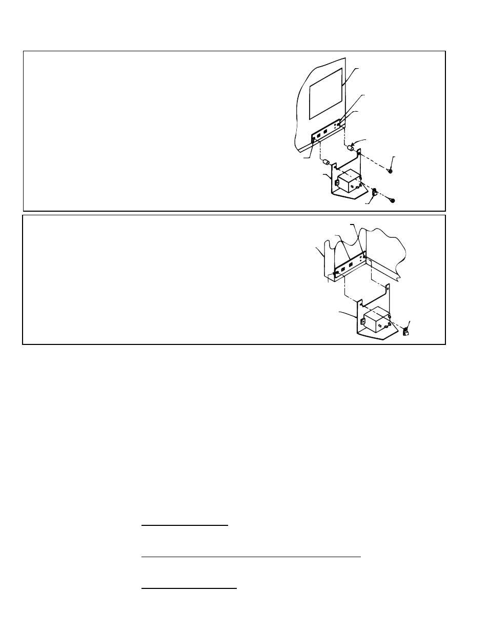
FIGURE 2C - Model VR
On the end of the burner/control box, remove and
discard the screws holding the thermostat terminal strip.
Use the screws and spacers in the option package to
attach the relay bracket and to re-attach the terminal
strip. Follow the sequence below, starting at the burner/
control box
-
first the terminal strip,
-
second the spacers,
-
third the relay bracket,
- and
fourth (on the left side only) – put the blue and
brown wires through the plastic cable clamp and
position the cable clamp on top of the relay bracket.
FIGURE 2D - Model F or B
On the rear of the heater, remove the screws
that hold the thermostat terminal strip. Slide
the relay bracket underneath the terminal strip.
Re-insert the screw on the right side. Put the
blue and brown wires into the plastic cable
clamp, and on the left end of the terminal strip,
position the cable clamp on top. Fasten with the
other screw.
Screw (remove to install)
Terminal Strip
Place wiring diagram
on lower right corner
of the outer side panel.
Relay Bracket
Assembly
Cable
Clamp
Screw (remove
to install)
NOTE: The 1" long screws and the spacers in the
option package will not be used.
4. Wiring Diagram Label – All Heaters
Installation
Instructions (cont'd)
See
FIGURE 3A, 3B, or 3C for Option CL31 and CL32 wiring diagram.
Model FIGURE Label
LDAP ................3A ...............208185
UDAP ................3B ...............197164
UDAS ................3B ...............197164
UDBP ................3B ...............197164
UDBS ................3B ...............197164
UEAS ................3B ...............197164
VR .....................3B ...............197164
F ........................3C ...............131127
B .......................3C ...............131127
Select the wiring diagram for the model of heater being installed. Check the
appropriate box on each diagram for the heater function (Primary or Secondary).
Adhere the label in the location specified below for the model of heater .
Packaged Model LDAP – Position the label (P/N 208185) on the inside of the access
panel. Wipe the area with a clean, dry cloth. Remove the backing and adhere the
wiring diagram.
Unit Heater Models UDAP, UDAS, UDBP, UDBS, and UEAS – Position the label
(
P/N 197164) on the bottom rear corner of the access panel. Wipe the area with a
clean, dry cloth. Remove the backing and adhere the wiring diagram.
Infrared Heater Model VR – Position the label on the rear of the burner box above
the terminal strip. Wipe the area with a clean, dry cloth. Remove the backing and
adhere the wiring diagram.
NOTE: The spacers are required to allow the access door to open.
3. Install a Relay or Relay Bracket Assembly (cont'd)
- B Option - Installation - Multiple Heater Control (Options CL31 and CL32) F Option - Installation - Multiple Heater Control (Options CL31 and CL32) UEAS Option - Installation - Multiple Heater Control (Options CL31 and CL32) UDBS Option - Installation - Multiple Heater Control (Options CL31 and CL32) UDBP Option - Installation - Multiple Heater Control (Options CL31 and CL32) UDAS Option - Installation - Multiple Heater Control (Options CL31 and CL32) UDAP Option - Installation - Multiple Heater Control (Options CL31 and CL32) LDAP Option - Installation - Multiple Heater Control (Options CL31 and CL32)