Check appropriate box, Primary heater secondary heater – Reznor VR Option - Installation - Multiple Heater Control (Options CL31 and CL32) User Manual
Page 7
Form I-OPT-MH, P/N 102247 R7, Page 7
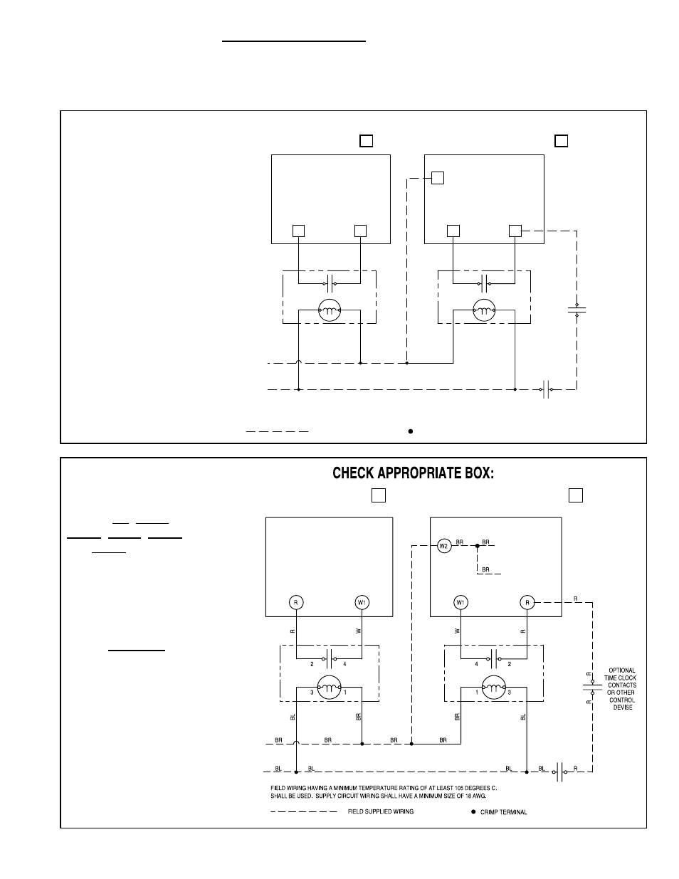
FIGURE 3A- Multiple
Heater Control Wiring
Diagram Label for Model
LDAP, P/N 208185
Label
208185
CHECK APPROPRIATE BOX:
PRIMARY HEATER
SECONDARY HEATER
SECONDARY
HEATER
4
2
3
1
PRIMARY
HEATER
1
4
3
2
1
W
1
W
R
R
7
CRIMP TERMINAL
BR
BR
BR
BR
R
L
B
L
B
L
B
L
B
R
R
CONTROL DEVICE
OR OTHER
THERMOSTAT
R
R
BL
W
RB
W
R
BL
BR
FIELD SUPPLIED WIRING
FIELD WIRING HAVING A MINIMUM TEMPERATURE RATING OF AT LEAST 105 DEGREES C.
SHALL BE USED. SUPPLY CIRCUIT WIRING SHALL HAVE A MINIMUM SIZE OF 18 AWG.
ADDITIONAL
SECONDARY HEATERS
TO
TIME CLOCK
CONTACTS
OPTIONAL
DEVISE
CONTROL
OR OTHER
WD# 189578
For future identification,
check appropriate box on
each wiring diagram label.
Unit Heater Models F and B – Position the label (P/N 131127) in the lower right
corner of the outer left side panel (left when facing the rear of the heater). Wipe the
area with a clean, dry cloth. Remove the backing and adhere the wiring diagram.
5. Control Wiring - All Models
Follow the diagram label to wire the controls.
FIGURE 3B - Multiple
Heater Control Wiring
Diagram Label for
Models VR, UDAP,
UDAS, UDBP, UDBS,
and UEAS, P/N 197164
PRIMARY HEATER
SECONDARY HEATER
SECONDARY
HEATER
PRIMARY HEATER
TO COMMON SIDE
OF TRANSFORMER
TO “COM” ON
DSI CONTROL
TO ADDITIONAL
SECONDAR
Y
HEA
TERS
THERMOSTAT
OR OTHER
CONTROL DEVICE
Label
197164
For future identification,
check appropriate box on
each wiring diagram label.
(NOTE: VR Models do
not have a "W2" terminal.
Splice between the DSI
control "COM" and 24V on
the transformer and use
the twist-on wire connector
provided to connect the
wires.
- B Option - Installation - Multiple Heater Control (Options CL31 and CL32) F Option - Installation - Multiple Heater Control (Options CL31 and CL32) UEAS Option - Installation - Multiple Heater Control (Options CL31 and CL32) UDBS Option - Installation - Multiple Heater Control (Options CL31 and CL32) UDBP Option - Installation - Multiple Heater Control (Options CL31 and CL32) UDAS Option - Installation - Multiple Heater Control (Options CL31 and CL32) UDAP Option - Installation - Multiple Heater Control (Options CL31 and CL32) LDAP Option - Installation - Multiple Heater Control (Options CL31 and CL32)