Installation instructions (cont'd) – Reznor VR Option - Installation - Multiple Heater Control (Options CL31 and CL32) User Manual
Page 4
Form I-OPT-MH, P/N 102247 R7, Page 4
Installation
Instructions (cont'd)
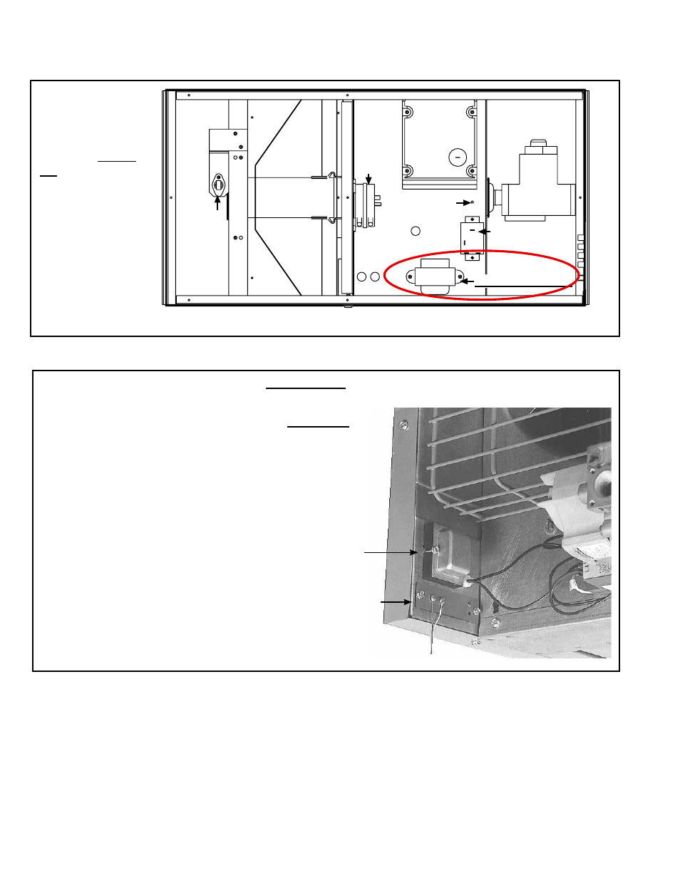
FIGURE 1C - Transformer Location, Model F or B "Primary" Heater
Rear View
Transformer
Terminal
Strip
Remove the left outer side panel
(left when facing the rear of the
heater), exposing the inner side
panel and the wiring.
Locate the factory-installed
transformer. Mark and disconnect
the wires. Remove the transformer.
Through the “large” hole in the
side panel (for mounting the
transformer), slide the Tinnerman
clips over the new transformer.
Attach with the screws included in
the kit. Connect the wires to the new
transformer.
Replace the outer side panel.
Gas
Valve
Relay
(Optional)
Ignition
Controller
Pressure Switch
Sp
ark
Electrode
TRANSFORMER
Burner Section
Control Section (Open this side only to
change transformer.)
24V T
erminal
Board
Ground
Screw
Burner
FIGURE 1B -
Bottom View
showing
Transformer
Location, Model
VR "Primary"
Heater
2. Change the Transformer (cont'd)
- B Option - Installation - Multiple Heater Control (Options CL31 and CL32) F Option - Installation - Multiple Heater Control (Options CL31 and CL32) UEAS Option - Installation - Multiple Heater Control (Options CL31 and CL32) UDBS Option - Installation - Multiple Heater Control (Options CL31 and CL32) UDBP Option - Installation - Multiple Heater Control (Options CL31 and CL32) UDAS Option - Installation - Multiple Heater Control (Options CL31 and CL32) UDAP Option - Installation - Multiple Heater Control (Options CL31 and CL32) LDAP Option - Installation - Multiple Heater Control (Options CL31 and CL32)