Installation instructions warning – Reznor VR Option - Installation - Multiple Heater Control (Options CL31 and CL32) User Manual
Page 3
Form I-OPT-MH, P/N 102247 R7, Page 3
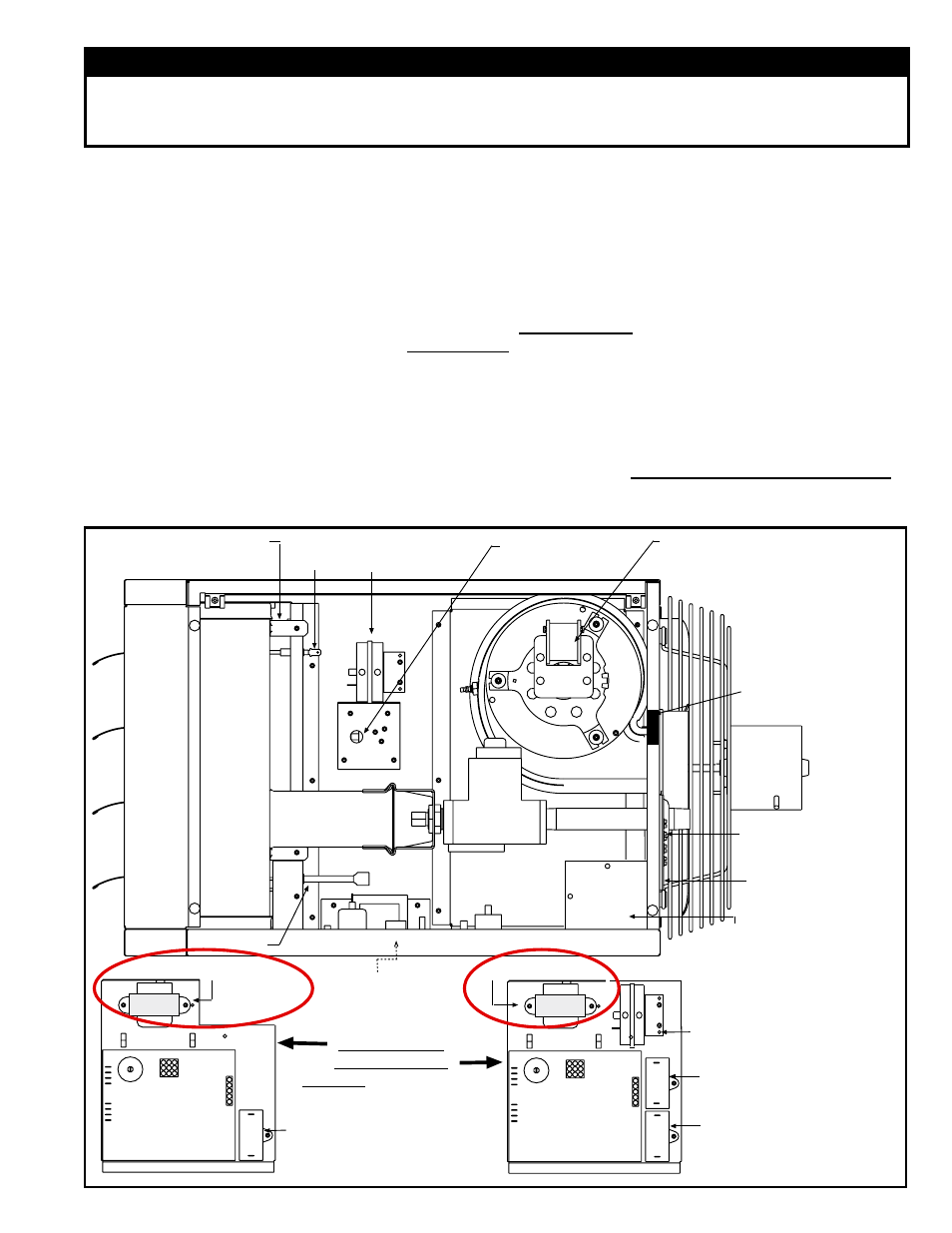
Pressure Switch
- Sizes 30-125
Venter Motor (Size 30-75
illustrated. Venter motor is in the
same location for all models,
but appearance is different.)
Fan
Motor
Gas Valve
TRANSFORMER
Circuit Board
(DSI Integrated
Control Module)
Optional Fan Motor
Capacitor (used with
208/230V and Option AL14)
High Temperature
Limit Control
Flame Rollout Switch
(UDAP and UDAS
Sizes 30-125 only)
Ignitor
Flame
Sensor
Burner
Assembly
Terminal
Board (24V)
TRANSFORMER
Circuit Board
(DSI Integrated
Control Module)
Fan Motor
Capacitor
Venter Motor
Capacitor
Pressure Switch
(Sizes 150-400)
Control Panel Assy
located on the
Control Compartment
Bottom
UDAP/S 30-125
UDAP/S 150-400
All UEAS - On the cabinet
bottom; control locations
are slightly different.
UDAS, UEAS, and
UDBS have a collar
for the combustion
air pipe (not shown)
Door Switch - UDAS,
UEAS, and UDBS only
Electrical Box - UDAS
and UDBS only
Remove cover to connect
supply and access discon-
nect switch wires. Always
replace cover.
Disconnect Switch
- UDAS, UEAS, and
UDBS only
FIGURE 1A - Control Compartment showing Transformer Location, Models UDAP, UDAS, and UEAS
"Primary" Heater
The transformer is mounted on the control board on the bottom of the control compartment.
These instructions are designed to assist a qualified electrician in installing this multiple
heater control kit. All electrical wiring and connections, including electrical grounding,
MUST be in accordance with the National Electric Code ANSI/NFPA No. 70 (latest edi-
tion) or, in Canada, with the Canadian Electrical Code, Part 1-C.S.A. Standard C22.1 In
addition, the installation must comply with local ordinances and applicable gas company
requirements.
Follow the instructions that apply to the option and model of heater.
1. Turn off the gas and electric power.
2. Change the Transformer (does not apply to Model LDAP, UDBP, or UDBS) –
applies to OPTION CL31 installation on the "Primary" unit only
Refer to the illustration
(FIGURE 1A, 1B, or 1C) for the unit being serviced.
Remove or open panels as required and locate the factory-installed transformer.
Mark and disconnect the wires. Remove the transformer.
Using the same screws (except Models F and B; see
FIGURE 1C), install the 35 or
40 VA transformer from the kit. Connect the wires. Close the panel.
Installation
Instructions
WARNING
Improper installation, adjustment, alteration, service or maintenance can cause property
damage, injury, or death. Read the installation, operation, and maintenance instructions
thoroughly before installing or servicing this equipment.
- B Option - Installation - Multiple Heater Control (Options CL31 and CL32) F Option - Installation - Multiple Heater Control (Options CL31 and CL32) UEAS Option - Installation - Multiple Heater Control (Options CL31 and CL32) UDBS Option - Installation - Multiple Heater Control (Options CL31 and CL32) UDBP Option - Installation - Multiple Heater Control (Options CL31 and CL32) UDAS Option - Installation - Multiple Heater Control (Options CL31 and CL32) UDAP Option - Installation - Multiple Heater Control (Options CL31 and CL32) LDAP Option - Installation - Multiple Heater Control (Options CL31 and CL32)