PRG Best Boy Field Service Manual User Manual
Page 94
86
BEST BOY 4000
®
SPOT LUMINAIRE FIELD SERVICE MANUAL
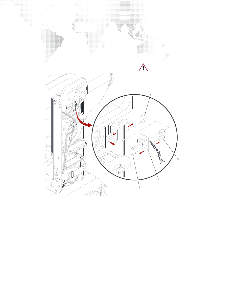
Step
7. At Tilt COT Sensor PCB, remove two 4-40 x 1/4" PFSS screws which secure standoffs to yoke.
Step
8. Remove Tilt COT Sensor Cable Assembly.
Step
9. Remove two 1/4" Hex Standoffs from PCB by removing two 4-40 x 1/4" PPSS screws.
Step 10. Install 1/4" Hex Standoffs on new Tilt COT Sensor PCB, applying Loctite 242 to screws/standoffs.
Step 11. Install new Tilt COT Sensor Cable Assembly by doing steps in reverse.
Figure 3-54: Removing Tilt COT Sensor PCB
4-40 x 1/4" PFSS Screw (2)
Tilt COT Sensor PCB Cable Assembly
1/4" Hex Standoff (2)
4-40 x 1/4" PPSS Screw (2)
- Apply Loctite 242
- Apply Loctite 242
CAUTION:
Use anti-static precautions
when working with PC boards.