Spot luminaire field service manual, Top view - cable layout – PRG Best Boy Field Service Manual User Manual
Page 82
74
BEST BOY 4000
®
SPOT LUMINAIRE FIELD SERVICE MANUAL
Step
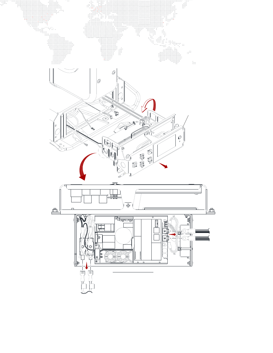
6. Flip Interface/LVS Assembly upside down as shown in Figure 3-44.
Step
7. Disconnect AC cables and LVS DC Output cables.
Step
8. Remove Interface/LVS Assembly
Step
9. Replace component by doing steps in reverse.
Figure 3-44: Removing Interface/LVS Assembly
+
w
w
w
.x
p
powe
r.
c
om
C
C
M
250P
S
1
2
+Ve R
OF
P/F
+5 V
e
Em
itter
-Ve
RO
F
P/F
-5 V
e
Colle
cto
r
_
XP
R
e
v L
e
ve
l:
6
S
e
ri
a
l No
.
F
0
945415
W
eek
N
o
.
45/
09
Se
ri
a
l N
o
M
ode
l No
LN
TOP VIEW - CABLE LAYOUT
BLK
RED
AC L
IN
E
AC
NEU
T
N
L
BLK
WH
T
F1
F2
FU
SE
FU
S
E
Interface/LVS Assembly
AC Cables
LVS DC
Output Cables