PRG Best Boy Field Service Manual User Manual
Page 60
52
BEST BOY 4000
®
SPOT LUMINAIRE FIELD SERVICE MANUAL
Step
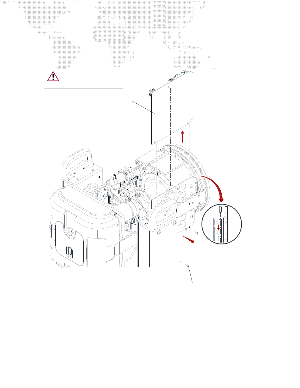
5. At bottom of Head Controller PCB, remove two 6-32 x 1/4" screws (Figure 3-26).
Step
6. Slide Head Controller PCB up and out of Head Assembly.
Step
7. Replace PCB by doing steps in reverse. When re-installing, insert PCB into slot of rails/retainers as shown
in Detail A below.
Figure 3-26: Removing Head Controller PCB
"A"
CRITICAL!
DETAIL
Head Controller PCB
6-32 x 1/4" Screw (2)
Insert PCB into slot of rails/retainers
when re-installing.
CAUTION:
Use anti-static precautions
when working with PC boards.