Switching frequency and pwm commands, Frequency_switch, Interleave – Maxim Integrated MAX15303 PMBus Command Set User Manual
Page 14
MAX15303 PMBus Command Set User’s Guide
Page 14 of 52
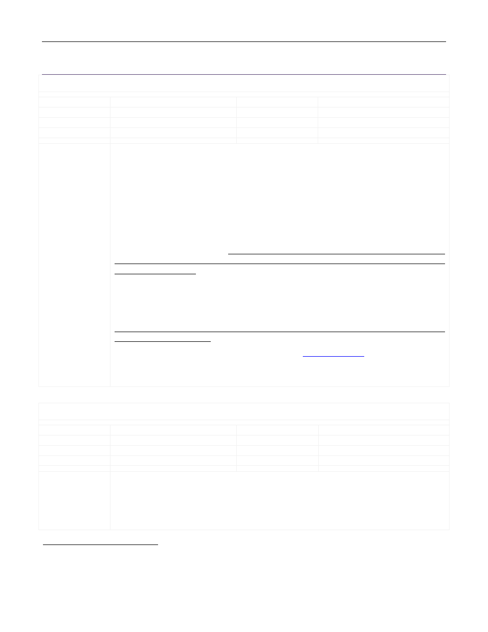
Switching Frequency and PWM Commands
FREQUENCY_SWITCH
Reference:
Standard Command
Lockable:
Yes
Command Code:
0x33
Format:
Linear
Data Bytes:
2
Units:
kHz
Transfer:
Read/Write Word
Factory Value:
0x0258 (600kHz)
Description/Notes: See Section 14.4 of the PMBus Specification Part II.
The factory value of 0x0258 (600kHz) will be overridden during initialization by the hardware (pin-
strap) value determined by the resistance to ground detected at the SYNC pin, unless a specific value
has been written to the User Store. The value of the SYNC pin resistance is measured only once
during initialization (power-up).
The MAX15303 can also synchronize to an external clock at the SYNC input. If the external clock is
present at or before power-up, the SYNC resistance reading will fail and FREQUENCY_SWITCH will be
set to 300kHz.
The MAX15303 has two different PWM “speed modes” to support FREQUENCY_SWITCH values at or
below 475kHz, and above 475kHz. It is important to ensure that FREQUENCY_SWITCH is set, either by
PMBus command or by successful resistor pin-strap, to a value that is within ±10% of the expected
external clock frequency.
If the external clock is present at the time of output enable, the operating memory value of
FREQUENCY_SWITCH will be updated to reflect the external clock frequency. If the external clock is
applied after enabling the output, the PWM will synchronize to the external clock, but
FREQUENCY_SWITCH will not be updated.
If the external clock crosses the 475kHz boundary while regulating, unexpected results or output
voltage transients may result.
The actual switching frequency can be obtained using the
command.
Wait at least 10ms for execution after sending the FREQUENCY_SWITCH command before sending
additional PMBus commands.
INTERLEAVE
Reference:
Standard Command
Lockable:
Yes
Command Code:
0x37
Format:
4 x 4-bit unsigned integer “nibbles”
Data Bytes:
2
Units:
N/A
Transfer:
Read/Write Word
Factory Value:
0x0000 (see Description)
Description/Notes: See Section 14.7 of the PMBus Specification Part II.
The INTERLEAVE command determines the phase delay of the MAX15303, measured from the rising
edge of an external clock applied at SYNC to the center of the PWM positive pulse.
The factory value of 0x0000 (zero degrees phase shift) will be overridden during initialization by the
hardware (pin-strap) value determined by the resistances to ground detected at the ADDR0 and
c
Because the MAX15303 has dual-edge modulation, the rising and falling edges of the PWM waveform both “move”
relative to the center of the high-side switch on-time.