Mini-mod-cnc overview, M4-cnc overview, Switch mode = target temperature – LAARS M4-Ext - Installation Manual User Manual
Page 3: Switch mode = outdoor temperature, Outdoor temp
Installation Manual
3
M4-CNC OvERviEW
In response to new advancement in condensing boiler design and size, many applications utilize multiple condensing boilers in
addition to the non-condensing boilers. That triggered Laars design of the M4-CNC. It is intended to manage the two groups of
boilers to maximize system efficiency at the lowest operating cost while maintaining the desired comfort. The M4-CNC operates each
group based on the Target temperature switching set point.
Depending on the actual Target Temperature, the M4-CNC will determine which group of boilers will be the lead and which group
will be the lag group. The Condensing Group of boilers will be the Lead group when the Target Temperature is below the Switching
Set Point. However, when the Target Temperature rises above the Switching Set Point, the Non-Condensing Boiler Group will be the
lead group and the Condensing Group will be the lag group.
Basically, the M4-CNC will allow the condensing group of boilers to operate as along as the Target Temperature is below the
Switching Set Point. See "Switch Set Point" on page 16. During that period, if additional output boilers are needed, the M4-CNC will
energize the non-condensing boilers to meet the load. See "Heavy Load Sequence 2nd Group" on page 17. When less output is required
the M4-CNC will de-energize the non-condensing boilers prior to de-energizing the condensing boilers.
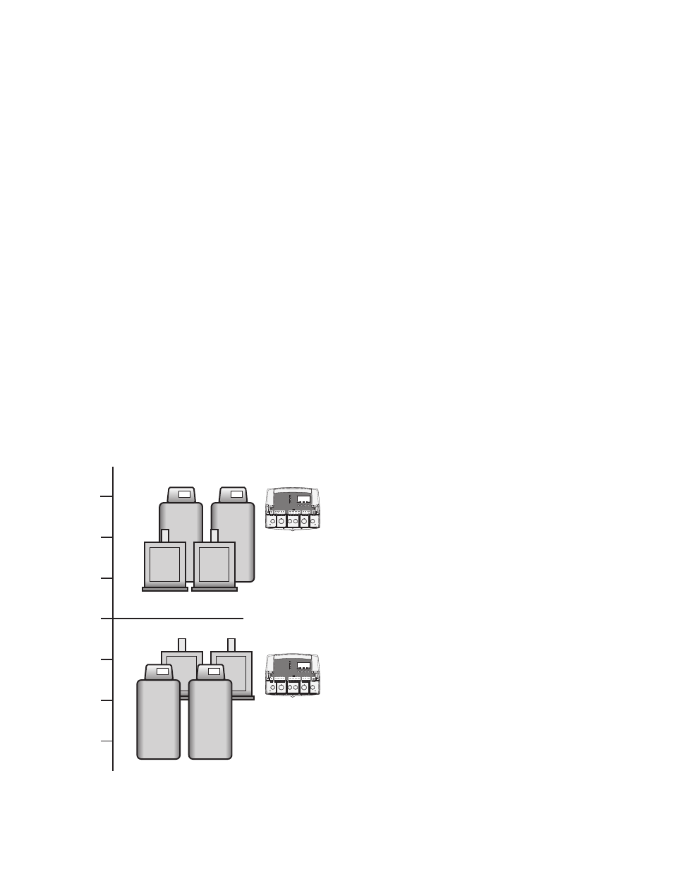
Above the Switch Set Point
Non-Condensing are the Lead Group
Condensing are the Lag Group
Target Switch
Set Point
= 120°F
Below the Switch Set Point
Condensing are the Lead Group
Non-Condensing are the Lag Group
120°F
140°F
100°F
SWITCH MODE = Target Temperature
SYSTEM
A
B
C
D
Condensing / Non-Condensing Control
1 2
RUN
PROGRAM
FOR ALL CIRCUITS
120VAC, 6A RESISTIVE
OUTPUT RATINGS:
1A PILOT DUTY, 15A TOTAL
115VAC 60Hz , 12VA MAX
INPUT RATINGS:
USE COPPER CONDUCTORS ONLY
DO NOT APPLY ANY VOLTAGE
TO INPUT TERMINALS
3 4 5 6 7 8 9 10 11 12
13
15
14
17
16
18
22
20
19
21
24
23
29
25
27
26
28
32
30 31
L N
-
+
+
T
T
O
O
RS-485
mA
GND
VLT
SYS
A
B
C
D
PWR
CUR / VLT
A
-
+
+
mA
GND
VLT
-
+
+
mA
GND
VLT
-
+
+
mA
GND
VLT
+
mA
TEMP
OUTDOOR
O
O
TEMP
SYSTEM
EXTENSION
MODULE
CUR / VLT
B
CUR / VLT
C
CUR / VLT
D
CAUTION: RISK OF ELECTRIC SHOCK
More than one disconnect switch may be required
to de-energize the equipment before servicing.
PROVE
/DHW
SHUTDOWN
/TSTAT
/SETBACK
OD=
25oF
SYS=
145oF
<>
B
100%
52%
COND
COND
NON-
COND
NON-
COND
NON-
COND
NON-
COND
COND
COND
SYSTEM
A
B
C
D
Condensing / Non-Condensing Control
1 2
RUN
PROGRAM
FOR ALL CIRCUITS
120VAC, 6A RESISTIVE
OUTPUT RATINGS:
1A PILOT DUTY, 15A TOTAL
115VAC 60Hz , 12VA MAX
INPUT RATINGS:
USE COPPER CONDUCTORS ONLY
DO NOT APPLY ANY VOLTAGE
TO INPUT TERMINALS
3 4 5 6 7 8 9 10 11 12
13
15
14
17
16
18
22
20
19
21
24
23
29
25
27
26
28
32
30 31
L N
-
+
+
T
T
O
O
RS-485
mA
GND
VLT
SYS
A
B
C
D
PWR
CUR / VLT
A
-
+
+
mA
GND
VLT
-
+
+
mA
GND
VLT
-
+
+
mA
GND
VLT
+
mA
TEMP
OUTDOOR
O
O
TEMP
SYSTEM
EXTENSION
MODULE
CUR / VLT
B
CUR / VLT
C
CUR / VLT
D
CAUTION: RISK OF ELECTRIC SHOCK
More than one disconnect switch may be required
to de-energize the equipment before servicing.
PROVE
/DHW
SHUTDOWN
/TSTAT
/SETBACK
OD=
25oF
SYS=
145oF
<>
B
100%
52%
Target
Temp
Above the Switch Set Point
Condensing are the Lead Group
Non-Condensing are the Lag Group
Outdoor Switch
Set Point
= 30°F
Below the Switch Set Point
Non-Condensing are the Lead Group
Condensing are the Lag Group
30°F
50°F
10°F
SWITCH MODE = Outdoor Temperature
COND
COND
NON-
COND
NON-
COND
NON-
COND
NON-
COND
COND
COND
SYSTEM
A
B
C
D
Condensing / Non-Condensing Control
1 2
RUN
PROGRAM
FOR ALL CIRCUITS
120VAC, 6A RESISTIVE
OUTPUT RATINGS:
1A PILOT DUTY, 15A TOTAL
115VAC 60Hz , 12VA MAX
INPUT RATINGS:
USE COPPER CONDUCTORS ONLY
DO NOT APPLY ANY VOLTAGE
TO INPUT TERMINALS
3 4 5 6 7 8 9 10 11 12
13
15
14
17
16
18
22
20
19
21
24
23
29
25
27
26
28
32
30 31
L N
-
+
+
T
T
O
O
RS-485
mA
GND
VLT
SYS
A
B
C
D
PWR
CUR / VLT
A
-
+
+
mA
GND
VLT
-
+
+
mA
GND
VLT
-
+
+
mA
GND
VLT
+
mA
TEMP
OUTDOOR
O
O
TEMP
SYSTEM
EXTENSION
MODULE
CUR / VLT
B
CUR / VLT
C
CUR / VLT
D
CAUTION: RISK OF ELECTRIC SHOCK
More than one disconnect switch may be required
to de-energize the equipment before servicing.
PROVE
/DHW
SHUTDOWN
/TSTAT
/SETBACK
OD=
25oF
SYS=
145oF
<>
B
100%
52%
SYSTEM
A
B
C
D
Condensing / Non-Condensing Control
1 2
RUN
PROGRAM
FOR ALL CIRCUITS
120VAC, 6A RESISTIVE
OUTPUT RATINGS:
1A PILOT DUTY, 15A TOTAL
115VAC 60Hz , 12VA MAX
INPUT RATINGS:
USE COPPER CONDUCTORS ONLY
DO NOT APPLY ANY VOLTAGE
TO INPUT TERMINALS
3 4 5 6 7 8 9 10 11 12
13
15
14
17
16
18
22
20
19
21
24
23
29
25
27
26
28
32
30 31
L N
-
+
+
T
T
O
O
RS-485
mA
GND
VLT
SYS
A
B
C
D
PWR
CUR / VLT
A
-
+
+
mA
GND
VLT
-
+
+
mA
GND
VLT
-
+
+
mA
GND
VLT
+
mA
TEMP
OUTDOOR
O
O
TEMP
SYSTEM
EXTENSION
MODULE
CUR / VLT
B
CUR / VLT
C
CUR / VLT
D
CAUTION: RISK OF ELECTRIC SHOCK
More than one disconnect switch may be required
to de-energize the equipment before servicing.
PROVE
/DHW
SHUTDOWN
/TSTAT
/SETBACK
OD=
25oF
SYS=
145oF
<>
B
100%
52%
Outdoor
Temp
LAARS Modulating Controls M4 & M4-EXT
HT# 059104-00 B