Wiring, Wiring the power, Wiring the sensors – LAARS M4-Ext - Installation Manual User Manual
Page 11: Wiring the shutdown, tstat, or setback, Warning, Mini-mod-cnc, Installation manual 11, Laars modulating controls m4 & m4-ext, Terminals 31, 32), A b c d
Installation Manual
11
WiRiNg
• All wiring must enter the enclosure through the bottom knockouts.
• Class 1 voltage wiring must utilize a different knockout and conduit from any Class 2 voltage wiring.
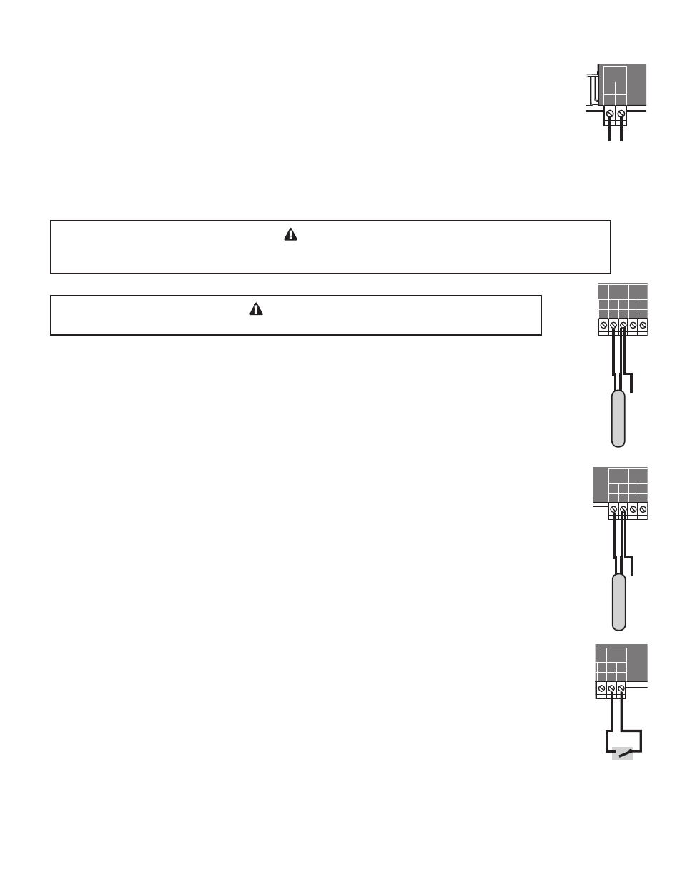
WiRiNg THE POWER
(TERMinALS 1, 2)
• Bring the 120VAC 60Hz power wires through the bottom left knockout of the enclosure.
• Connect the hot line to terminal marked L.
• Connect the neutral line to the terminal marked N.
• Laars recommends installing a surge suppressor on the power source to the M4-CNC.
WARNiNg
Class 1 voltages must enter the enclosure through a different opening from any Class 2 voltage wiring.
Laars recommends installing a surge suppressor on the power source to the M4-CNC.
SYSTEM
A
B
C
D
Condensing / Non-Condensing Control
1 2
RUN
PROGRAM
FOR ALL CIRCUITS
120VAC, 6A RESISTIVE
OUTPUT RATINGS:
1A PILOT DUTY, 15A TOTAL
115VAC 60Hz , 12VA MAX
INPUT RATINGS:
USE COPPER CONDUCTORS ONLY
DO NOT APPLY ANY VOLTAGE
TO INPUT TERMINALS
3 4 5 6 7 8 9 10 11 12
13
15
14
17
16
18
22
20
19
21
24
23
29
25
27
26
28
32
30 31
L N
-
+
+
T
T
O
O
RS-485
mA
GND
VLT
SYS
A
B
C
D
PWR
CUR / VLT
A
-
+
+
mA
GND
VLT
-
+
+
mA
GND
VLT
-
+
+
mA
GND
VLT
+
mA
TEMP
OUTDOOR
O
O
TEMP
SYSTEM
EXTENSION
MODULE
CUR / VLT
B
CUR / VLT
C
CUR / VLT
D
CAUTION: RISK OF ELECTRIC SHOCK
More than one disconnect switch may be required
to de-energize the equipment before servicing.
PROVE
/DHW
SHUTDOWN
/TSTAT
/SETBACK
ENCLOSED
ENERGY
MANAGEMENT
EQUIPMENT
99RA
OD=
25
o
F
SYS=
145
o
F
<>
B
100%
52%
Mini-MOD-CNC
Line
Neutral
120VAC
Power Source
WiRiNg THE SENSORS
WARNiNg
Connect the shield at the control terminal end and cut the shield wire at the sensor end.
SYSTEM SENSOR WiRiNg
(TERMinALS 27, 28)
• A M4-CNC must be connected to a System temperature sensor (CA002400 or equivalent) located in the common
header. The sensor must be inserted in a 3/8 ID well (CA002500 or equivalent).
• Temperature sensor wires can be extended up to 500’ by splicing its wires with a shielded 2-conductor cable
(Belden #8760 or equivalent (#18/2)).
• Temperature sensors have no polarity. Connect the two wires from the sensor to the M4-CNC terminals marked
SYSTEM TEMP 27, 28.
• Connect the sensor shield to the circled terminal 28 with one of the sensor wires.
SYSTEM
A
B
C
D
Condensing / Non-Condensing Control
1 2
RUN
PROGRAM
FOR ALL CIRCUITS
120VAC, 6A RESISTIVE
OUTPUT RATINGS:
1A PILOT DUTY, 15A TOTAL
115VAC 60Hz , 12VA MAX
INPUT RATINGS:
USE COPPER CONDUCTORS ONLY
DO NOT APPLY ANY VOLTAGE
TO INPUT TERMINALS
3 4 5 6 7 8 9 10 11 12
13
15
14
17
16
18
22
20
19
21
24
23
29
25
27
26
28
32
30 31
L N
-
+
+
T
T
O
O
RS-485
mA
GND
VLT
SYS
A
B
C
D
PWR
CUR / VLT
A
-
+
+
mA
GND
VLT
-
+
+
mA
GND
VLT
-
+
+
mA
GND
VLT
+
mA
TEMP
OUTDOOR
O
O
TEMP
SYSTEM
EXTENSION
MODULE
CUR / VLT
B
CUR / VLT
C
CUR / VLT
D
CAUTION: RISK OF ELECTRIC SHOCK
More than one disconnect switch may be required
to de-energize the equipment before servicing.
PROVE
/DHW
SHUTDOWN
/TSTAT
/SETBACK
ENCLOSED
ENERGY
MANAGEMENT
EQUIPMENT
99RA
OD=
25
o
F
SYS=
145
o
F
<>
B
100%
52%
Mini-MOD-CNC
System Sensor
Sensor Shield
SYSTEM
A
B
C
D
Condensing / Non-Condensing Control
1 2
RUN
PROGRAM
FOR ALL CIRCUITS
120VAC, 6A RESISTIVE
OUTPUT RATINGS:
1A PILOT DUTY, 15A TOTAL
115VAC 60Hz , 12VA MAX
INPUT RATINGS:
USE COPPER CONDUCTORS ONLY
DO NOT APPLY ANY VOLTAGE
TO INPUT TERMINALS
3 4 5 6 7 8 9 10 11 12
13
15
14
17
16
18
22
20
19
21
24
23
29
25
27
26
28
32
30 31
L N
-
+
+
T
T
O
O
RS-485
mA
GND
VLT
SYS
A
B
C
D
PWR
CUR / VLT
A
-
+
+
mA
GND
VLT
-
+
+
mA
GND
VLT
-
+
+
mA
GND
VLT
+
mA
TEMP
OUTDOOR
O
O
TEMP
SYSTEM
EXTENSION
MODULE
CUR / VLT
B
CUR / VLT
C
CUR / VLT
D
CAUTION: RISK OF ELECTRIC SHOCK
More than one disconnect switch may be required
to de-energize the equipment before servicing.
PROVE
/DHW
SHUTDOWN
/TSTAT
/SETBACK
ENCLOSED
ENERGY
MANAGEMENT
EQUIPMENT
99RA
OD=
25
o
F
SYS=
145
o
F
<>
B
100%
52%
Mini-MOD-CNC
Outdoor Sensor
Sensor Shield
OUTdOOR SENSOR WiRiNg
(TERMinALS 25, 26)
• The M4-CNC will vary the system Set Point based on outdoor temperature. In addition, the outdoor sensor is used
as an Outdoor Cutoff. The M4-CNC will disable all boilers when the outdoor temperature is above the adjustable
Outdoor Cutoff temperature.
• For an outdoor sensor use the outdoor sensor provided (CA006500).
• The sensor wires can be extended up to 500’ using shielded 2-conductor cable (Belden #8760 or equivalent (#18/2)).
• Temperature sensors have no polarity. Connect the wires from the outdoor sensor to the M4-CNC terminals marked
OUTDOOR TEMP - 25, 26.
• Connect the shield to the circled terminal 26 with one of the sensor wires.
WiRiNg THE SHUTdOWN, TSTAT, OR SETBACk
(TERMinALS 31, 32)
• The Shutdown will be available when selected as the Shutdown/Tstat/Setback mode from the Startup menu. See
"Shutdown/Tstat/Setback Mode" on page 19. This will provide the user with an adjustable Day/Night Schedule. See
"Day/Night Schedules" on page 28.
• The Shutdown feature can be used whenever it is desirable to turn off the M4-CNC stage outputs from a remote
location or another controller (i.e. EMS input).
• The Tstat option, when selected from the Shutdown/Tstat/Setback startup menu, offer the capability of controlling
the operation of the M4-CNC based on a thermostat input. This will provide the user with an adjustable Day/Night
Schedule.
• The thermostat will send the M4-CNC a call for heat by shorting terminals 31 and 32.
SYSTEM
A
B
C
D
Condensing / Non-Condensing Control
1 2
RUN
PROGRAM
FOR ALL CIRCUITS
120VAC, 6A RESISTIVE
OUTPUT RATINGS:
1A PILOT DUTY, 15A TOTAL
115VAC 60Hz , 12VA MAX
INPUT RATINGS:
USE COPPER CONDUCTORS ONLY
DO NOT APPLY ANY VOLTAGE
TO INPUT TERMINALS
3 4 5 6 7 8 9 10 11 12
13
15
14
17
16
18
22
20
19
21
24
23
29
25
27
26
28
32
30 31
L N
-
+
+
T
T
O
O
RS-485
mA
GND
VLT
SYS
A
B
C
D
PWR
CUR / VLT
A
-
+
+
mA
GND
VLT
-
+
+
mA
GND
VLT
-
+
+
mA
GND
VLT
+
mA
TEMP
OUTDOOR
O
O
TEMP
SYSTEM
EXTENSION
MODULE
CUR / VLT
B
CUR / VLT
C
CUR / VLT
D
CAUTION: RISK OF ELECTRIC SHOCK
More than one disconnect switch may be required
to de-energize the equipment before servicing.
PROVE
/DHW
SHUTDOWN
/TSTAT
/SETBACK
ENCLOSED
ENERGY
MANAGEMENT
EQUIPMENT
99RA
OD=
25
o
F
SYS=
145
o
F
<>
B
100%
52%
Mini-MOD-CNC
Shutdown,
T-Stat, or
Setback Signal
LAARS Modulating Controls M4 & M4-EXT
HT# 059104-00 B