Extension layout, M4ext, M4-lhs installation and operation manual – LAARS M4-LHS - Installation Manual User Manual
Page 7
HT# 059295-00
A
M4-LHS installation and Operation Manual
7
ParT NuMBEr # Ca004400
Ext A
M4Ext
FULL MODULATION SEQUENCING EXTENSION
F
H
J
Power
E
G
I
Comm
K
M
O
L
N
P
CAUTION:
Risk of Electric Shock.
More than one disconnect switch may be required
to de-energize the equipment before servicing.
INPUT RATINGS:
115VAC 60Hz, 12VA MAX
Use Copper Conductors Only.
OUTPUT RATINGS:
120VAC, 6A RESISTIVE
1A PILOT DUTY, 15A TOTAL
FOR ALL CIRCUITS
ENCLOSED
ENERGY
MANAGEMENT
EQUIPMENT
LISTED
99RA
C
US
Ext B
PWR
L N
1 2
E
3 4
F
5 6
G
7 8
H
9 10
I
11 12
EXTENSION
MODULE
RS-485
15
14
VLT
mA
CUR / VLT
18
17
16
VLT
mA
GND
CUR / VLT
21
20
19
VLT
mA
GND
CUR / VLT
24
23
22
VLT
mA
GND
CUR / VLT
J
11 12
K
M
O
L
N
P
E
F
G
H
K
M
L
N
13
GND
16
GND
19
GND
22
GND
27
26
VLT
mA
CUR / VLT
30
29
16
VLT
mA
GND
CUR / VLT
25
GND
28
GND
I
J
O
P
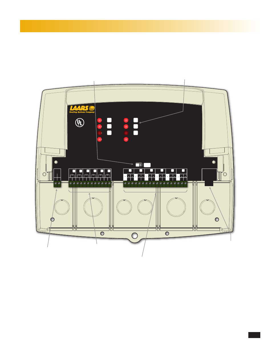
LED indicates the
associated relay status.
Extension Selection Switch to determine
Stage letters and LED colors.
Ext-A Stages E - J and all LEDs are Green
Ext-B Stages K - P and all LEDs are Red
This switch is covered with the Wiring Enclosure.
120VAC Power
Six N.O. Boiler startup relay
outputs. Each is wired in series
with each boiler's limit circuit.
Six modulation/staging outputs can be
4-20mA or Voltage. Go to the control Startup
Menu to determine the type of output for each stage.
Connect to any M4-LHS
and additional Extension panels to add
additional stages using a RJ11 cable only
(cable provided with M4Ext).
ExTENSiON LaYOuT