Connecting to bacnet interface module, Activate the battery, X-bac – LAARS M4-LHS - Installation Manual User Manual
Page 16: Alert, M4-lhs, M4ext, Extension, M4-lhs installation and operation manual, Battery, Bacnet interface module
HT# 059295-00
A
16
M4-LHS installation and Operation Manual
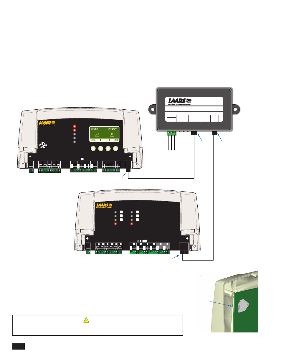
Connecting to BaCnet interface Module
• The M4-LHS can communicate to BACnet MSTP networks when used the X-BAC BACnet Interface Module (CA009100). The
module must be purchased separately.
• The BACnet Interface Module comes with an RJ45 cable.
• Both the M4-LHS and the BACnet Interface Module are equipped with a RJ45 socket (RS485) to connect to communicate to each
other.
• The Interface BACnet Module must be wired to the BACnet MSTP network using the RS485 terminals A, GND, and B.
• If both an extension panel and the BACnet Interface Module are to be used, connect the RJ11 socket on the BACnet Interface
Module to the extension.
• Set the BACnet parameters. See "BACnet MSTP Communication Menu" on page 26.
BACnet Interface Module
MSTP
1
2
3
A GND B
PRODUCT
COMM
RS485
X-BAC
A
B
C
D
1 2
RUN
PROGRAM
DO NOT APPLY ANY VOLTAGE
TO INPUT TERMINALS
3 4 5 6 7 8 9 10 11 12
13
15
14
17
16
18
20
19
21
24
23
29
25
27
26
28
32
30 31
L N
-
+
+
T
T
O
O
RS-485
mA
GND
VLT
SYS
A
B
C
D
PWR
CUR / VLT
A
-
+
+
mA
GND
VLT
-
+
+
mA
GND
VLT
+
+
mA
22
-
GND
VLT
+
mA
TEMP
OUTDOOR
O
O
TEMP
SYSTEM
EXTENSION
MODULE
CUR / VLT
B
CUR / VLT
C
CUR / VLT
D
PROVE
/DHW
SHUTDOWN
/SETBACK
FOR ALL CIRCUITS
120VAC, 6A RESISTIVE
OUTPUT RATINGS:
1A PILOT DUTY, 15A TOTAL
115VAC 60Hz , 30VA MAX
INPUT RATINGS:
USE COPPER WIRE,
CLASS 1 WIRE ONLY.
CAUTION: RISK OF ELECTRIC SHOCK
More than one disconnect switch may be required
to de-energize the equipment before servicing.
ENCLOSED
ENERGY
MANAGEMENT
EQUIPMENT
99RA
/TSTAT
M4-LHS
HYBRID CONTROL
RJ45 Communication Cable
RJ45 Cable
Extension
RJ11 Extension Cable
RJ45
RJ11
RJ45
RJ11
F
H
J
Power
CAUTION:
Risk of Electric Shock.
More than one disconnect switch may be required
to de-energize the equipment before servicing.
PWR
L N
1 2
E
3 4
F
5 6
G
7 8
H
9 10
I
11 12
EXTENSION
MODULE
RS-485
Ext A
INPUT RATINGS:
115VAC 60Hz, 12VA MAX
Use Copper Conductors Only.
OUTPUT RATINGS:
120VAC, 6A RESISTIVE
1A PILOT DUTY, 15A TOTAL
FOR ALL CIRCUITS
E
G
I
Comm
Ext B
K
M
O
L
N
P
17
16
VLT
mA
CUR / VLT
20
19
16
VLT
mA
GND
CUR / VLT
23
22
19
VLT
mA
GND
CUR / VLT
26
25
22
VLT
mA
GND
CUR / VLT
J
13 14
K
M
O
L
N
P
E
F
G
H
K
M
L
N
15
GND
18
GND
21
GND
24
GND
29
28
VLT
mA
CUR / VLT
32
31
16
VLT
mA
GND
CUR / VLT
27
GND
30
GND
I
J
O
P
M4Ext
FULL MODULATION SEQUENCING EXTENSION
A (+)
Ground
B (-)
To BACnet
MSTP
aCTiVaTE THE BaTTErY
• The battery enables to control to maintain the clock time.
• Unscrew and remove the Enclosure Display Module to reveal the back of the control
CPU Board.
• Remove the plastic strap that covers the battery. The battery holder contacts should be
touching the battery. The control has a coin Lithium battery (CR2032) that is used to
maintain the control's time during power outages. This battery can maintain the clock for
up to a total of 100 days.
aLErT
Do not install the battery unless you plan to keep the control continuously powered. If the
control has no power, the battery will lose its charge in 100 days.
Battery