Wiring the boilers, Wiring boiler activation or on/off staging boilers, Wiring multi-stage boilers – LAARS M4-LHS - Installation Manual User Manual
Page 14: Wiring to modulating boilers, Wiring the 4-20ma modulating boilers, Wiring voltage modulating boilers, M4-lhs, Warning, Multi-stage boiler, Modulating boiler (modulating boiler type)
HT# 059295-00
A
14
M4-LHS installation and Operation Manual
Wiring the Boilers
• When wiring Condensing and Non-Condensing boilers make sure that the Condensing boilers use the first
stages and the Non-Condensing boilers use the following stages. That is, if the installation had two Condensing
Modulating boilers and two Non-Condensing Staging On/Off boilers, Stage A and B must be used by the
Condensing boilers while Stage C and D must be used by the Non-Condensing boilers.
Wiring Boiler activation or On/Off Staging Boilers
(A Terminals 5, 6), (B Terminals 7, 8), ...
• Each boiler output has a Normally Open (N.O.) dry-contact relay. They do not source any power.
• Wire the N.O. relay contacts in series with the unit’s limit circuit.
• Note that some modulating boilers may not require the use of these outputs.
Boiler Enable
Output
Boiler
SYSTEM
A
B
C
D
1 2
RUN
PROGRAM
DO NOT APPLY ANY VOLTAGE
TO INPUT TERMINALS
3 4 5 6 7 8 9 10 11 12
13
15
14
17
16
18
20
19
21
24
23
29
25
27
26
28
32
30 31
L N
-
+
+
T
T
O
O
RS-485
mA
GND
VLT
SYS
A
B
C
D
PWR
CUR / VLT
A
-
+
+
mA
GND
VLT
-
+
+
mA
GND
VLT
+
+
mA
22
-
GND
VLT
+
mA
TEMP
OUTDOOR
O
O
TEMP
SYSTEM
EXTENSION
MODULE
CUR / VLT
B
CUR / VLT
C
CUR / VLT
D
PROVE
/DHW
SHUTDOWN
/SETBACK
FOR ALL CIRCUITS
120VAC, 6A RESISTIVE
OUTPUT RATINGS:
1A PILOT DUTY, 15A TOTAL
115VAC 60Hz , 30VA MAX
INPUT RATINGS:
USE COPPER WIRE,
CLASS 1 WIRE ONLY.
CAUTION
: RISK OF ELECTRIC SHOCK
More than one disconnect switch may be required
to de-energize the equipment before servicing.
ENCLOSED
ENERGY
MANAGEMENT
EQUIPMENT
99RA
/TSTAT
M4-LHS
HYBRID CONTROL
Wiring Multi-Stage Boilers
(For Staging Boiler Types Only) See Page 19
• Each stage on a multi-stage boiler must use one of the N.O. relays.
• Note that on the display of the M4-LHS each multi-stage boiler will
consist of a multiple letters.
• Each stage output has one Normally Open (N.O.) relay contact that
does not source any power.
WarNiNg
Class 1 voltages must enter the enclosure through a different opening from any Class 2 voltage wiring.
OD=
55
o
F SYS=
142
o
F
<
CD
HI
LOW
STAGE ◄ ► MENU
Multi-Stage Boiler
2-Stage Boiler
Low
High
SYSTEM
A
B
C
D
1 2
RUN
PROGRAM
DO NOT APPLY ANY VOLTAGE
TO INPUT TERMINALS
3 4 5 6 7 8 9 10 11 12
13
15
14
17
16
18
20
19
21
24
23
29
25
27
26
28
32
30 31
L N
-
+
+
T
T
O
O
RS-485
mA
GND
VLT
SYS
A
B
C
D
PWR
CUR / VLT
A
-
+
+
mA
GND
VLT
-
+
+
mA
GND
VLT
+
+
mA
22
-
GND
VLT
+
mA
TEMP
OUTDOOR
O
O
TEMP
SYSTEM
EXTENSION
MODULE
CUR / VLT
B
CUR / VLT
C
CUR / VLT
D
PROVE
/DHW
SHUTDOWN
/SETBACK
FOR ALL CIRCUITS
120VAC, 6A RESISTIVE
OUTPUT RATINGS:
1A PILOT DUTY, 15A TOTAL
115VAC 60Hz , 30VA MAX
INPUT RATINGS:
USE COPPER WIRE,
CLASS 1 WIRE ONLY.
CAUTION
: RISK OF ELECTRIC SHOCK
More than one disconnect switch may be required
to de-energize the equipment before servicing.
ENCLOSED
ENERGY
MANAGEMENT
EQUIPMENT
99RA
/TSTAT
M4-LHS
HYBRID CONTROL
Wiring to Modulating Boilers
page 23. Some modulating boilers may require the use of the stage output relays in addition to the modulating output.
WarNiNg
The Modulating Output Type must be set to match the boiler modulating
signal prior to wiring the boiler signal to avoid control or equipment damage.
Wiring the 4-20ma Modulating Boilers
(A Terminals 13, 14), (B Terminals 16, 17),...
• The M4-LHS can operate up to four 4-20 mA modulating motors.
• The Extension can operate up to six 4-20 mA modulating motors.
• The M4-LHS and the Extension sources excitation voltage for the
4-20mA signal.
• Wire the (-) from the boiler modulating motor to the (GND) terminal
on the M4-LHS. That is for boiler A, the modulating (GND) terminal
will be 13.
• Wire the (+) from the boiler modulating motor to the (mA+) terminal
on the M4-LHS. That is for boiler A, the modulating (mA+) terminal
will be 14.
OD=
55
o
F SYS=
142
o
F
B
80%
50%
STAGE ◄ ► MENU
Modulating Boiler (Modulating
Boiler Type)
Boiler 4-20mA
Modulation Output
4-20mA
Burner
Motor
-
+
SYSTEM
A
B
C
D
1 2
RUN
PROGRAM
DO NOT APPLY ANY VOLTAGE
TO INPUT TERMINALS
3 4 5 6 7 8 9 10 11 12
13
15
14
17
16
18
20
19
21
24
23
29
25
27
26
28
32
30 31
L N
-
+
+
T
T
O
O
RS-485
mA
GND
VLT
SYS
A
B
C
D
PWR
CUR / VLT
A
-
+
+
mA
GND
VLT
-
+
+
mA
GND
VLT
+
+
mA
22
-
GND
VLT
+
mA
TEMP
OUTDOOR
O
O
TEMP
SYSTEM
EXTENSION
MODULE
CUR / VLT
B
CUR / VLT
C
CUR / VLT
D
PROVE
/DHW
SHUTDOWN
/SETBACK
FOR ALL CIRCUITS
120VAC, 6A RESISTIVE
OUTPUT RATINGS:
1A PILOT DUTY, 15A TOTAL
115VAC 60Hz , 30VA MAX
INPUT RATINGS:
USE COPPER WIRE,
CLASS 1 WIRE ONLY.
CAUTION
: RISK OF ELECTRIC SHOCK
More than one disconnect switch may be required
to de-energize the equipment before servicing.
ENCLOSED
ENERGY
MANAGEMENT
EQUIPMENT
99RA
/TSTAT
M4-LHS
HYBRID CONTROL
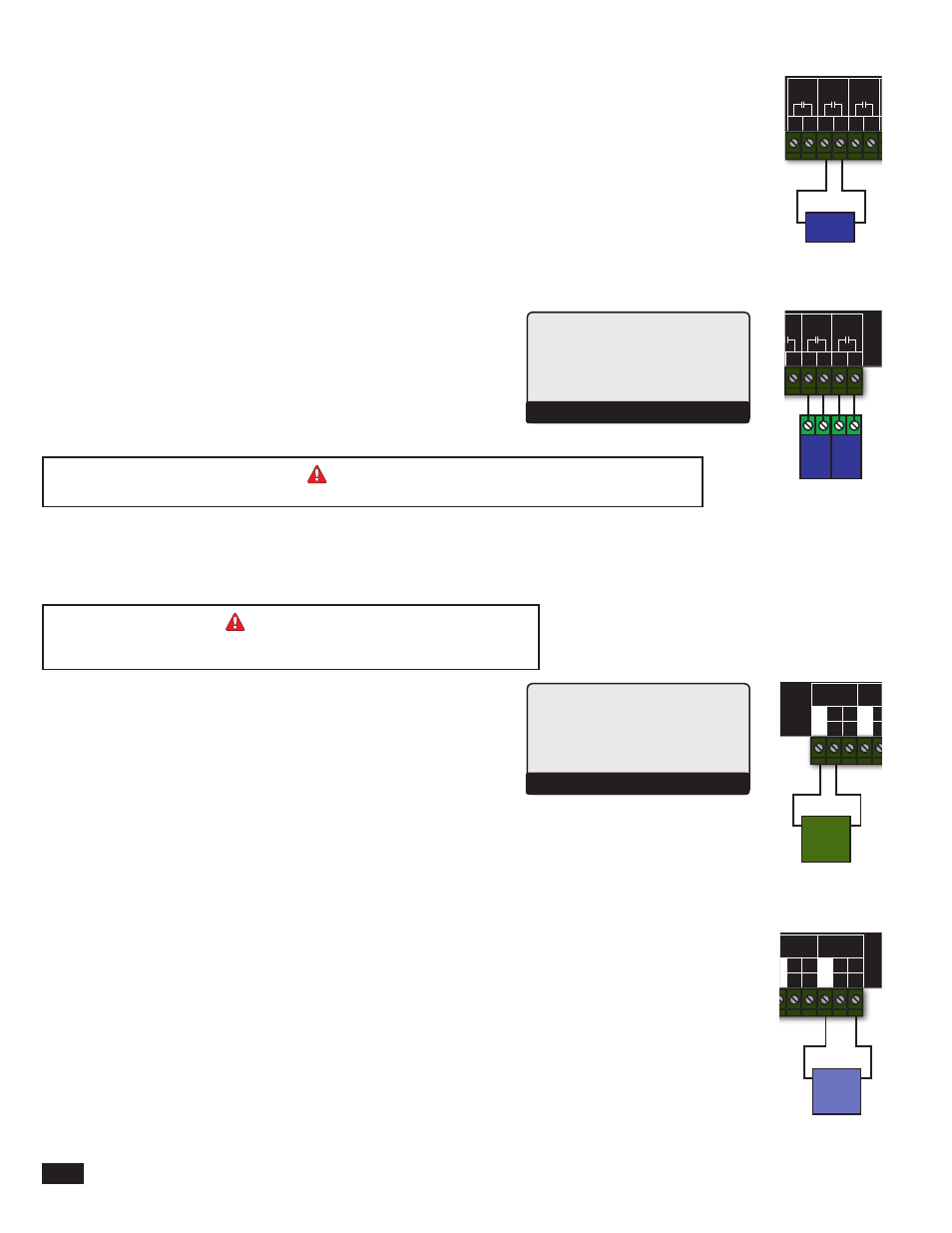
Wiring Voltage Modulating Boilers
(A Terminals 13, 15), (B Terminals 16, 18),...
• The M4-LHS can operate up to four 0-10V modulating motors.
• The Extension can operate up to six 0-10V modulating motors.
• Wire the (GND) from the boiler modulating motor to the (GND) terminal on the M4-LHS. For boiler D, the
modulating (GND) terminal is be 22.
• Wire the (VLT+) from the boiler modulating motor to the (VLT+)terminal on the M4-LHS. For boiler D, the
modulating (VLT+) terminal is be 23.
Boiler Voltage
Modulation Output
Voltage
Burner
Motor
GND
V+
SYSTEM
A
B
C
D
1 2
RUN
PROGRAM
DO NOT APPLY ANY VOLTAGE
TO INPUT TERMINALS
3 4 5 6 7 8 9 10 11 12
13
15
14
17
16
18
20
19
21
24
23
29
25
27
26
28
32
30 31
L N
-
+
+
T
T
O
O
RS-485
mA
GND
VLT
SYS
A
B
C
D
PWR
CUR / VLT
A
-
+
+
mA
GND
VLT
-
+
+
mA
GND
VLT
+
+
mA
22
-
GND
VLT
+
mA
TEMP
OUTDOOR
O
O
TEMP
SYSTEM
EXTENSION
MODULE
CUR / VLT
B
CUR / VLT
C
CUR / VLT
D
PROVE
/DHW
SHUTDOWN
/SETBACK
FOR ALL CIRCUITS
120VAC, 6A RESISTIVE
OUTPUT RATINGS:
1A PILOT DUTY, 15A TOTAL
115VAC 60Hz , 30VA MAX
INPUT RATINGS:
USE COPPER WIRE,
CLASS 1 WIRE ONLY.
CAUTION
: RISK OF ELECTRIC SHOCK
More than one disconnect switch may be required
to de-energize the equipment before servicing.
ENCLOSED
ENERGY
MANAGEMENT
EQUIPMENT
99RA
/TSTAT
M4-LHS
HYBRID CONTROL