Table 5 — chilled water coil circuiting data, Fig. 23 — typical direct-expansion row split coil – Carrier 39LB User Manual
Page 17
17
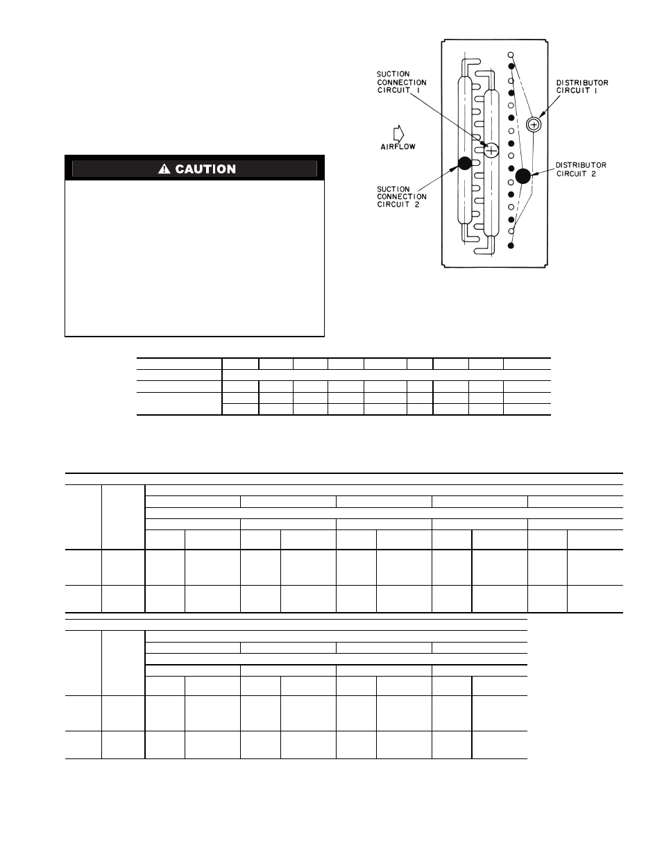
Refrigerant Piping, Direct-Expansion (DX)
Coils (Fig. 23) —
Direct-expansion coils are divided into
2 or 4 splits depending upon the unit size and coil circuiting.
See Table 7 for coil circuiting data. Each split requires its own
distributor nozzle, expansion valve, and suction piping. Suction
connections are on the air entering side when the coil is proper-
ly installed. Matching distributor connections for each coil split
are on the air leaving side. See unit label or certified drawing to
assure connection to matching suction and liquid connections.
See Table 8 for distributor part numbers.
Table 4 — Hot Water Coil Circuiting Data
LEGEND
NOTE: All hot water coils have 1
1
/
2
-in. MPT.
Table 5 — Chilled Water Coil Circuiting Data
LEGEND
NOTES:
1. Connection sizes are MPT — inches.
2. Sizes 21-25 have 2 coils.
Direct-expansion coils are shipped pressurized with dry
air. Release pressure from each coil split through valves in
protective caps before removing caps.
Do not leave piping open to the atmosphere unnecessar-
ily. Water and water vapor are detrimental to the refrigerant
system. Until the piping is complete, recap the system and
charge with nitrogen at the end of each workday. Clean all
piping connections before soldering joints.
The lower split of face split coils should be first on, last
off.
Row split coils utilize special intertwined circuits (as
shown in Fig. 23); either split of these row split coils can be
first on, last off.
39L UNIT SIZE
03
06
08
10
12
15
18
21
25
No. of Circuits
1-ROW H
6
8
10
10
10
13
15
15
13
2-ROW H
F
6
8
10
10
10
13
15
15
13
12
16
20
20
20
26
30
30
36
F
— Full Circuit
H
— Half Circuit
LARGE FACE AREA (39LA, 39LD)
COIL
TYPE
CIRCUIT
UNIT SIZE
03
06
08
10
12
Face Area (sq ft)
3.63
5.90
7.90
9.54
11.18
No.
Circuits
Connection
Size
No.
Circuits
Connection
Size
No.
Circuits
Connection
Size
No.
Circuits
Connection
Size
No.
Circuits
Connection
Size
4-ROW
Q
4
1
1
/
2
5
1
1
/
2
—
—
—
—
—
—
H
8
1
1
/
2
10
1
1
/
2
12
1
1
/
2
12
1
1
/
2
12
1
1
/
2
F
16
1
1
/
2
20
1
1
/
2
24
2
1
/
2
24
2
1
/
2
24
2
1
/
2
D
—
—
—
—
—
—
—
—
—
—
6-ROW
H
8
1
1
/
2
10
1
1
/
2
12
1
1
/
2
12
1
1
/
2
12
1
1
/
2
F
16
1
1
/
2
20
1
1
/
2
24
2
1
/
2
24
2
1
/
2
24
2
1
/
2
D
—
—
—
—
36
2
1
/
2
36
2
1
/
2
36
2
1
/
2
LARGE FACE AREA (39LA, 39LD)
COIL
TYPE
CIRCUIT
UNIT SIZE
15
18
21
25
Face Area (sq ft)
14.91
17.71
21.60
25.00
No.
Circuits
Connection
Size
No.
Circuits
Connection
Size
No.
Circuits
Connection
Size
No.
Circuits
Connection
Size
4-ROW
Q
—
—
—
—
—
—
—
—
H
16
1
1
/
2
19
1
1
/
2
19
1
1
/
2
22
1
1
/
2
F
32
2
1
/
2
38
2
1
/
2
38
2
1
/
2
44
2
1
/
2
D
—
—
—
—
76
2
1
/
2
88
2
1
/
2
6-ROW
H
16
1
1
/
2
19
1
1
/
2
19
1
1
/
2
—
—
F
32
2
1
/
2
38
2
1
/
2
38
2
1
/
2
44
2
1
/
2
D
48
2
1
/
2
57
2
1
/
2
57
2
1
/
2
66
2
1
/
2
D
— Double Circuit
F
— Full Circuit
H
— Half Circuit
Q
— Quarter Circuit
Fig. 23 — Typical Direct-Expansion
Row Split Coil