Notice, Replacement parts, In. deflection is 5 – Carrier 39LB User Manual
Page 13: Fig. 15 — fan belt tension data
13
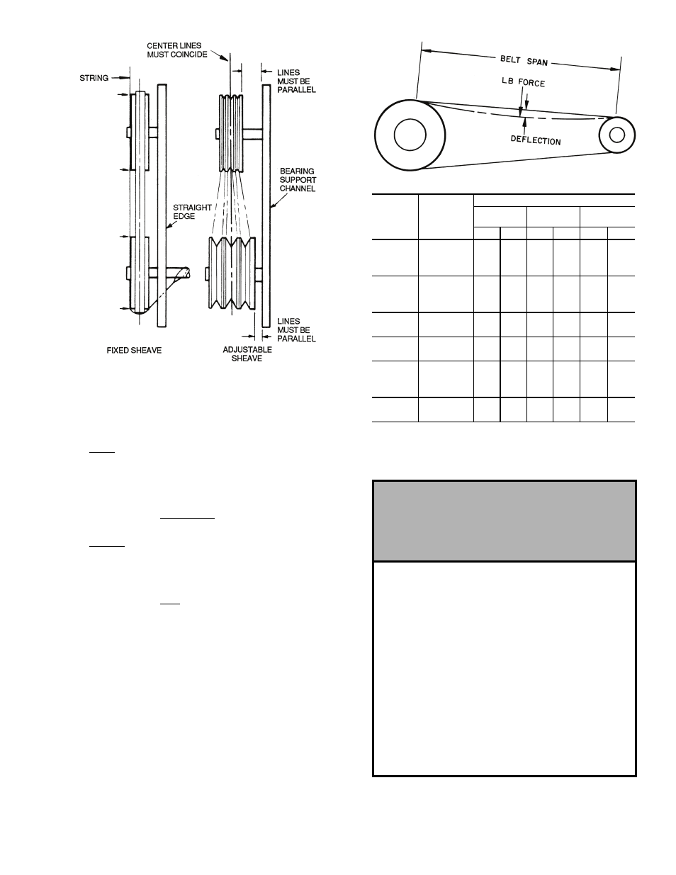
6. To determine correct belt tension, use the deflection
formula given below and the tension data from Fig. 15 as
follows:
EXAMPLE:
Given
Belt Span
16 in.
Belt Cross-Section A, Super Belt
Small Sheave PD
5 in.
Solution
1. From Fig. 15 find that deflection force for type A, super
belt with 5-in. small sheave PD is 4 to 5
1
/
2
lb.
2.
3. Increase or decrease belt tension until force required for
1
/
4
-in. deflection is 5
1
/
2
lb.
Check belt tension at least twice during first operating
day. Readjust as required to maintain belt tension within
the recommended range.
With correct belt tension, belts may slip and squeal
momentarily on start up. This slippage is normal and disap-
pears after unit reaches operating speed. Excessive belt tension
shortens belt life and may cause bearing and shaft damage.
After run-in, set belt tension at lowest tension at which belts
will not slip during operation.
Record information on the label (Fig. 16) found on the door
of the fan section.
Deflection =
(Belt Span)
64
Deflection =
16
64
Fig. 14 — Sheave Alignment
PD — Pitch Diameter, inches
Fig. 15 — Fan Belt Tension Data
BELT
CROSS
SECTION
SMALL
SHEAVE
PD RANGE
(in.)
DEFLECTION FORCE — LB
Super
Belts
Notch
Belts
Steel Cable
Belts
Min
Max
Min
Max
Min
Max
A
3.0- 3.6
3
4
1
/
4
3
7
/
8
5
1
/
2
3
4
3.8- 4.8
3
1
/
2
5
4
1
/
2
6
1
/
4
3
3
/
4
4
3
/
4
5.0- 7.0
4
5
1
/
2
5
6
7
/
8
4
1
/
4
5
1
/
4
B
3.4- 4.2
4
5
1
/
2
5
3
/
4
8
4
1
/
2
5
1
/
2
4.4- 5.6
5
1
/
8
7
1
/
8
6
1
/
2
9
1
/
8
5
3
/
4
7
1
/
4
5.8- 8.6
6
3
/
8
8
3
/
4
7
3
/
8
10
1
/
8
7
8
3
/
4
C
7.0- 9.4
11
1
/
4
14
3
/
8
13
3
/
4
17
7
/
8
11
1
/
4
14
9.6-16.0
14
1
/
8
18
1
/
2
15
1
/
4
20
1
/
4
14
1
/
4
17
3
/
4
3V
2.65-3.65
3
1
/
2
5
3
7
/
8
5
1
/
2
—
—
4.12-6.90
4
3
/
4
6
7
/
8
5
1
/
4
7
7
/
8
—
—
5V
4.40-6.70
—
—
10
15
—
—
7.1-10.9
10
1
/
2
15
3
/
4
12
7
/
8
18
3
/
4
—
—
11.8-16.0
13
19
1
/
2
15
22
—
—
8V
12.5-17.0
27
40
1
/
2
—
—
—
—
18.0-22.4
30
45
—
—
—
—
Fig. 16 — Fan Section Label
NOTICE
TENSION BELTS TO SPECIFICATION
SHOWN ON DRIVE LABEL. OVER
TENSIONING BELTS WILL SEVERELY
REDUCE BELT AND BEARING LIFE.
REPLACEMENT PARTS
BEARINGS
DRIVE
_______________________
FREE ________________________
SHAFT
________________________
WHEEL ________________________
INLET CONE ____________________
TO ORDER REPLACEMENT PARTS,
CONTACT: RCD
(REPLACEMENT COMPONENTS DIVISION)
1-800-443-4410