Carrier 39LB User Manual
Page 12
12
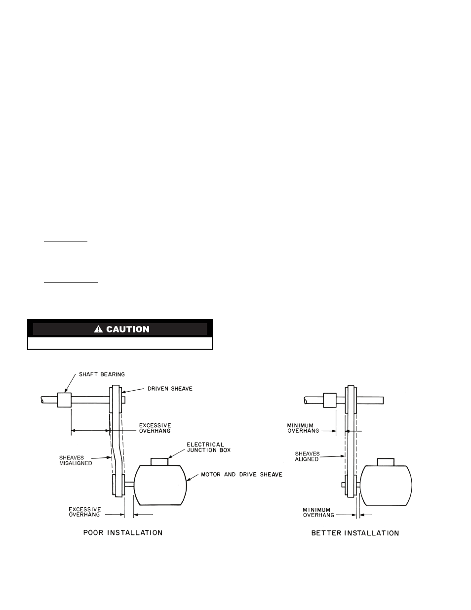
When field installing or replacing sheaves, install sheaves
on fan shaft and motor shaft for minimum overhang. (See
Fig. 13.) Use care when mounting sheave on fan shaft; too
much force may damage bearing. Remove rust-preventative
coating or oil from shaft. Make sure shaft is clean and free of
burrs. Add grease or lubricant to bore of sheave before
installing.
The 39L fan, shaft, and drive pulley are balanced as a com-
plete assembly to a high degree of accuracy. If excessive unit
vibration is present after fan pulley replacement, the unit must
be rebalanced. For drive ratio changes, always reselect the mo-
tor pulley — do not change the fan pulley.
ALIGNMENT — Make sure that fan shafts and motor shafts
are parallel and level. The most common causes of mis-
alignment are nonparallel shafts and improperly located
sheaves. Where shafts are not parallel, belts on one side are
drawn tighter and pull more than their share of the load. As a
result, these belts wear out faster, requiring the entire set to be
replaced before it has given maximum service. If misalignment
is in the sheave, belts will enter and leave the grooves at an
angle, causing excessive belt cover and sheave wear.
1. Shaft alignment can be checked by measuring the
distance between the shafts at 3 or more locations. If the
distances are equal, then the shafts will be parallel.
2. Sheave alignment:
Fixed sheaves — To check the location of the fixed
sheaves on the shafts, a straightedge or a piece of string
can be used. If the sheaves are properly lined up the string
will touch them at the points indicated by the arrows in
Fig. 14.
Adjustable sheave — To check the location of adjustable
sheave on shaft, make sure that the centerlines of both
sheaves are in line and parallel with the bearing support
channel. See Fig. 14. Adjustable pitch drives are installed
on the motor shaft.
3. Rotating each sheave a half revolution will determine
whether the sheave is wobbly or the drive shaft is bent.
Correct any misalignment.
4. With sheaves aligned, tighten cap screws evenly and
progressively.
NOTE: There should be a
1
/
8
-in. to
1
/
4
-in. gap between
the mating part hub and the bushing flange. If gap is
closed, the bushing is probably the wrong size.
5. With taper-lock bushed hubs, be sure the bushing bolts
are tightened evenly to prevent side-to-side pulley wob-
ble. Check by rotating sheaves and rechecking sheave
alignment. When substituting field-supplied sheaves for
factory-supplied sheaves, consider that the fan shaft
sheave has been factory balanced with fan and shaft as an
assembly. For this reason, substitution of motor sheave is
prefer-able for final speed adjustment.
Install V-Belts —
When installing or replacing belts, al-
ways use a complete set of new belts. Mixing old and new belts
will result in the premature wear or breakage of the newer
belts.
1. Always adjust the motor position so that V-belts can be
installed without stretching over grooves. Forcing belts
can result in uneven stretching and a mismatched set of
belts.
2. Do not allow belt to bottom out in sheave.
3. Tighten belts by turning motor-adjusting jackscrews.
Turn each jackscrew an equal number of turns.
4. Equalize belt slack so that it is on the same side of belt for
all belts. Failure to do so may result in uneven belt
stretching.
5. Tension new drives at the maximum deflection force
recommended (Fig. 15).
With adjustable sheave, do not exceed maximum fan rpm.
Fig. 13 — Determining Sheave-Shaft Overhang