Am loop antenna connection, B) fm wire antenna connection, Outdoor antenna – Philips FW540C User Manual
Page 11: Speakers connection, D) rear speakers' connection, D center speaker, 0 subwoofer out connection, G) connecting other, Equipment to your system, 0 ac power supply
Attention! The text in this document has been recognized automatically. To view the original document, you can use the "Original mode".
PREPARATION
® AM Loop Antenna
Connection
Connect the supplied loop antenna to the
AM ANTENNA terminal. Place the AM loop
antenna far away from the system and
adjust its position for the best reception,
(
b
) FM Wire Antenna
Connection
Connect the supplied FM wire antenna to
the FM ANTENNA 300 Ì2 terminal. Adjust
the position of the FM antenna for the best
reception.
Outdoor Antenna
For better FM stereo reception, connect an
outdoor FM antenna to the FM ANTENNA
300 Q terminal using a 300 Ì2 dipole wire.
© Speakers Connection
* Connect the right speaker to Front
terminal R, with the red wire to + and
the black wire to —.
» Connect the left speaker to Front
terminal L, with the red wire to + and
the black wire to —.
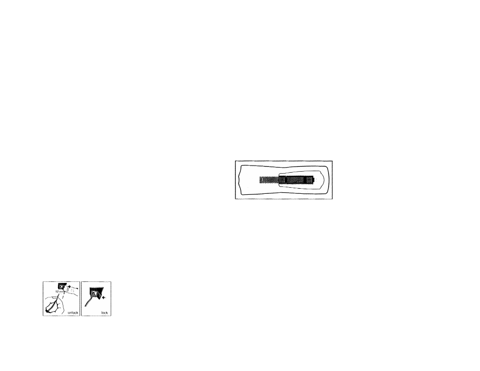
' Clip the
stripped
portion of
the
speaker
wire as
shown.
(D) Rear Speakers' Connection
Connect the black (non-marked) wires to
the black REAR SURROUND terminals and
the white (marked wires) to the grey REAR
SURROUND terminals.
(D Center Speaker
Connection
(for FW748Ponly)
Connect the black (non-marked) wires to
the black CENTER terminal and the blue
(marked wires) to the blue CENTER
terminal,
0
Subwoofer Out Connection
Connect the optional active subwoofer to
the SUBWOOFER OUT terminal. The
subwoofer reproduces just the low bass
effect (e.g. explosions, the rumble of
spaceships, etc,). Be sure to follow the
instructions supplied with the subwoofer.
(G) Connecting other
equipment to your system
You can connect the audio left and right
OUT terminals of a TV, VCR, Laser Disc
player or DVD player to the AUX IN
terminals at the rear of the system.
0 AC Power Supply
After all other connections have been
made, connect the AC power cord to the
system and to the wall outlet.
Inserting batteries into the
Remote Control
• Insert the batteries (Type ROB or AA)
into the remote control as shown in the
battery compartment.
To avoid damage from possible battery
leakage, remove dead batteries or
batteries that will not be used for a long
time. For replacement, use type ROB or
AA batteries.