Appendix a: networking connection, Witch, Rj-45 – Interlogix MC252-1P-1CX User Manual
Page 17: Ssignments, Able, A.1 switch’s rj-45 pin assignments, A.2 rj-45 cable pin assignments
17
APPENDIX A: NETWORKING CONNECTION
A.1 Switch’s RJ-45 Pin Assignments
10/100Mbps, 10/100Base-TX
RJ-45 Connector pin assignment
Contact
MDI
Media Dependant
Interface
MDI-X
Media Dependant
Interface -Cross
1
Tx + (transmit)
Rx + (receive)
2
Tx - (transmit)
Rx - (receive)
3
Rx + (receive)
Tx + (transmit)
4, 5
Not used
6
Rx - (receive)
Tx - (transmit)
7, 8
Not used
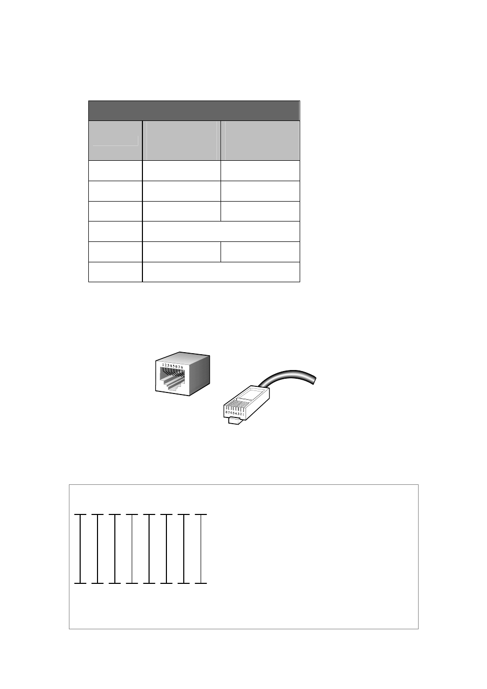
A.2 RJ-45 Cable Pin Assignments
The standard RJ-45 receptacle/connector
There are 8 wires on a standard UTP/STP cable and each wire is color-coded. The following shows the
pin allocation and color of straight cable and crossover cable connection:
Straight Cable
SIDE 1
SIDE2
SIDE 1
1
2
3
4
5
6
7
8
1
2
3
4
5
6
7
8
SIDE 2
1 = White / Orange
2 = Orange
3 = White / Green
4 = Blue
5 = White / Blue
6 = Green
7 = White / Brown
8 = Brown
1 = White / Orange
2 = Orange
3 = White / Green
4 = Blue
5 = White / Blue
6 = Green
7 = White / Brown
8 = Brown
Crossover Cable
SIDE 1
SIDE2