3 power over coaxial extender rear panel – Interlogix MC252-1P-1CX User Manual
Page 12
12
RJ-45 10/100Base-TX Interfaces
LED
Color
Function
Light: indicates the extender is successfully connecting to the network
at 100Mbps.
100
Green
OFF: indicates the extender is successfully connecting to the network
at 10Mbps.
LNK/ACT
Green
Blink: indicates the extender is actively sending or receiving data over
that port.
RJ-45 PoE Indicators
LED
Color
Model
Function
MC252-1T-1CXP
Light: indicates the RJ-45 port is receiving the PoE
Power.
PoE IN
Green
MC252-1P-1CX
Light: indicates the BNC connector is receiving the
PoE Power.
PoE Out
Green
MC252-1P-1CX
Light: indicates the RJ-45 Port is providing PoE
power
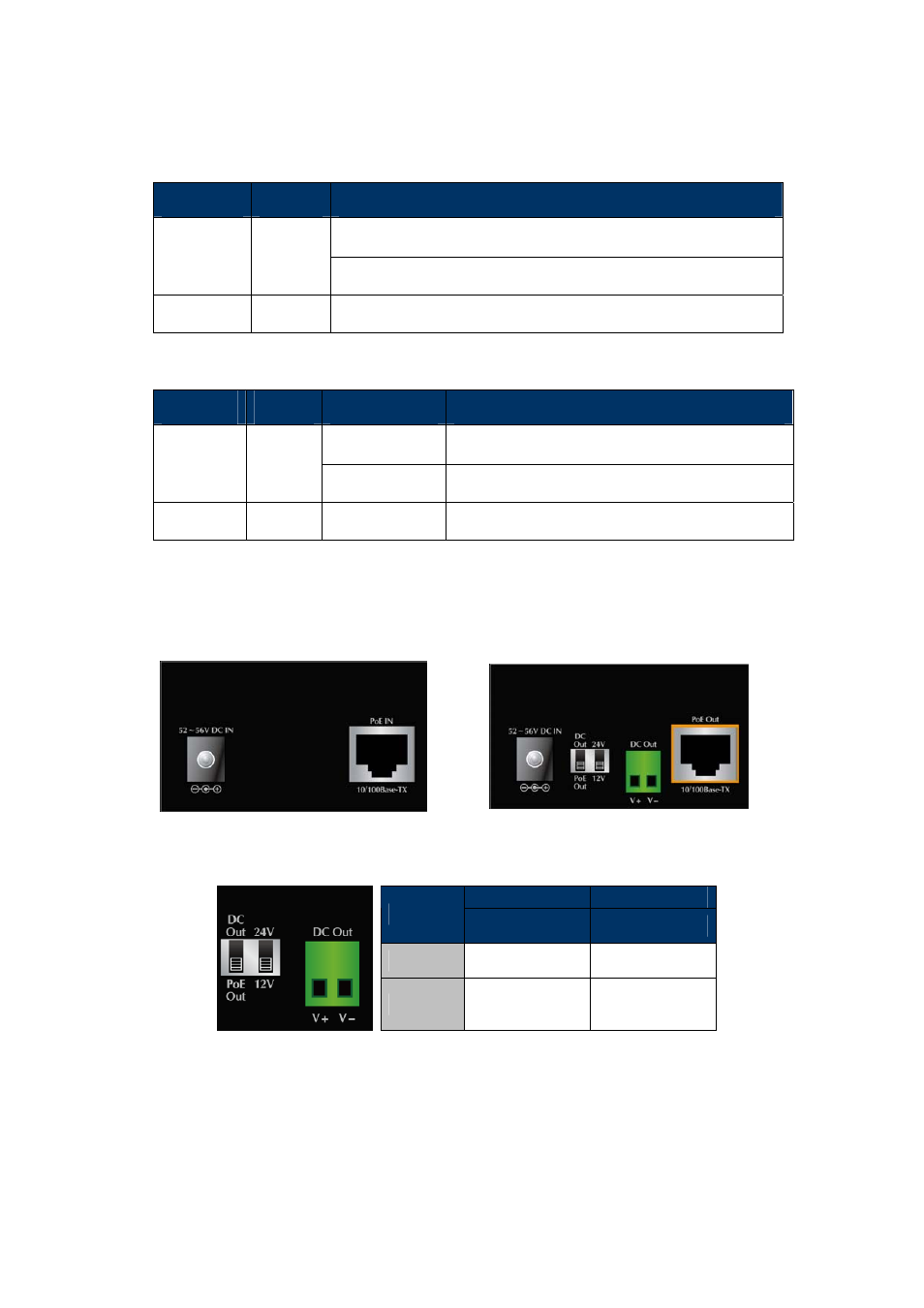
2.1.3 Power over Coaxial Extender Rear Panel
Figure 2-3 and Figure 2-4
show the rear panels of the MC252-1T-1CXP and MC252-1P-1CX Industrial
Power over Coaxial Extenders.
Figure 2-3:
MC252-1T-1CXPrear panel
Figure 2-3:
MC252-1P-1CX rear panel
MC252-1P-1CX Rear Panel: DIP Switch Setting
DIP-1
DIP-2
Power Output
Voltage
OFF
DC Out
24V
ON
PoE Out
(default)
12V
(default)
MC252-1P-1CX Rear Panel: 2-Pin Terminal Block