1 power over coaxial extender front panel, 2 led indicators – Interlogix MC252-1P-1CX User Manual
Page 11
11
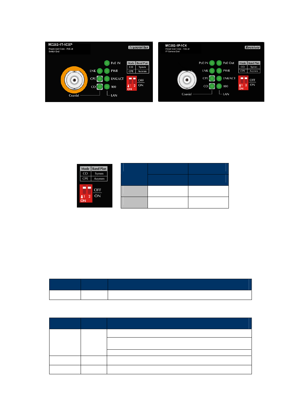
2.1.1 Power over Coaxial Extender Front Panel
Figure 2-1
and
Figure 2-2
show the front panels of the MC252-1T-1CXP and MC252-1P-1CX Industrial
Power over Coaxial Extenders.
Figure 2-1: MC252-1T-1CXP front panel Figure 2-2: MC252-1P-1CX front panel
Front Panel DIP Switch Setting
The front panels of the MC252-1T-1CXP and MC252-1P-1CX provide one 2-DIP switch which is for
configuring coaxial link CO/CPE mode and Band plan function.
Refer to the table below to know about the 2-DIP switch settings and descriptions:
DIP-1
DIP-2
Mode
Band Plan
OFF
CO Symmetric
ON
CPE Asymmetric
Symmetric means upstream and downstream rate are similar and Asymmetric means upstream and
downstream rate are not the same. The CO mode stands for Central Office (meaning the switch side)
and CPE mode is for Customer Premises Equipment (meaning camera side)
2.1.2 LED Indicators
System
LED
Color
Function
PWR
Green
Light: indicates the power is on.
Coaxial / VDSL2 Interfaces
LED
Color
Function
Light: indicates that the coaxial link is established.
Fast Blink: indicates that the coaxial link is at training status (about 10
seconds).
LNK
Green
Slow Blink: indicates that the coaxial link is at idle status.
CO
Green
Light: indicates the coaxial Bridge is running at CO mode.
CPE
Green
Light: indicates the coaxial Bridge is running at CPE mode.