2 system layout – IC Realtime IP High Speed PTZ Dome Camera with 36X Zoom and WDR (ICIPZ3601WDR) User Manual
Page 10
3
2 Cable Connection
2.1 Combination Cable Connection
The combination cable includes the network cable, audio/video cable, RS485 cable and alarm input/output
cable. Please refer to the labels on the cable for detailed information.
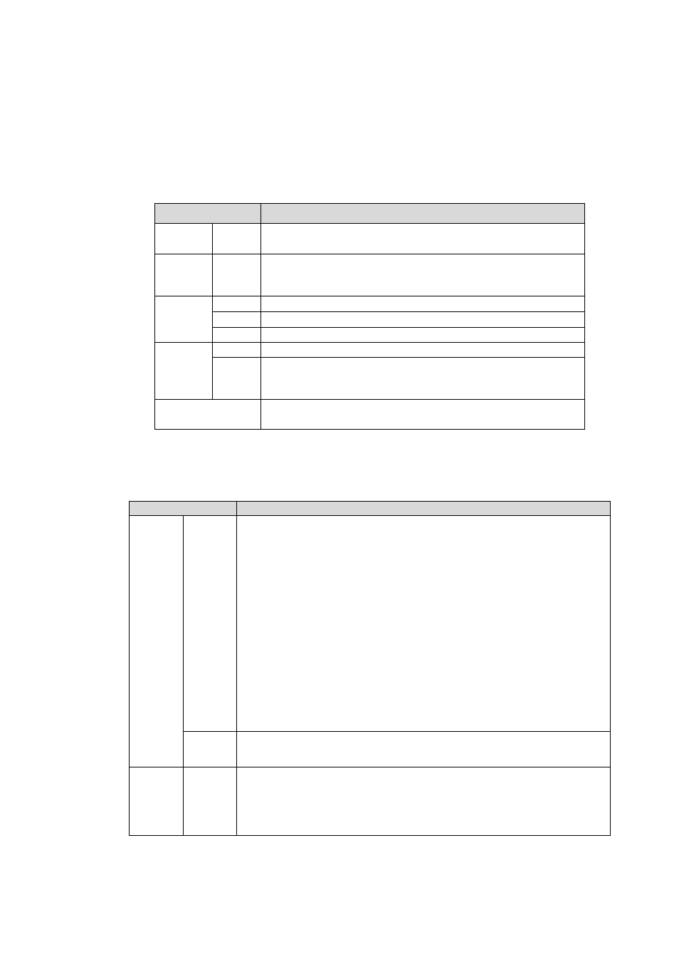
Please refer to the following sheet for RS485, audio/video port, power port and network port information.
Name
Function
POWER
GND
z
Power port. Connect to the power cable.
z
GND port.
485A
485B
RS485 remote control
OUT Audio
output
GND
GND port
AUDIO
IN
Audio input
GND Video
GND
Video
out
OUT
Video output.
You can connect cable to this port if you want to use the
analog video output.
LAN
Network port. Connect to the network cable.
Please refer to the following sheet for alarm input and output information.
z
Please note the IE6 does not support alarm upload function. Please use IE7 or higher version.
z
If it is your first time to boot up the WEB on the Windows 7 OS, please right click the Internet
Explorer icon on the desktop and then select “Run as Administrator”.
Name
Function
1-2
z
Two alarm input channels. They are to receive relay signal from
the external alarm source. You can go to dome menu to activate
specified preset or patter.
z
When the activation mode is NO (normal open), dome alarms
when there is low voltage. High voltage will not activate the
alarm.
z
When the activation mode is NC (normal close), dome alarms
when there is high voltage. Low voltage will not activate the
alarm.
Note:
z
Dome alarm input message is ground mode.
z
Dome alarm input signal are two modes: normal open and
normal close.
ALARM
IN
GND
Alarm input ground end.
ALARM
OUT
1
One-channel alarm output channel. When there is an alarm from
current channel, system activates relay or not.
Alarm output relay default setup is NO.
2.2 System Layout