Heckler&Koch MR762A1-LRP User Manual
Page 8
14
15
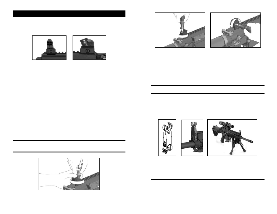
SECTION 4 — SIGHTS, SIGHT ADjUSTMENT, AND AIMING
MR762A1 rifles can accommodate a wide variety of optical and mechanical (iron) sights.
For models with HK Diopter rotary sight sets, the sights are installed on the MIL-STD-
1913 (Picatinny) rail with a Phillips #2 screwdriver or the HK sight tool (Fig. 5 & 6). Do not
over tighten the screws.
Fig. 5 – Front Diopter Sight Fig. 6 – Rear Diopter Sight
For optimal sight use and the longest sight radius, the front sight is installed on the
most forward portion of the MIL-STD-1913 rail and the rear sight is installed on the
most rearward portion of the MIL-STD-1913 rail (located on the upper receiver). Sight
adjustment is as follows:
1. Place target 100 meters (109.3 yards) downrange
2. Rotate rear drum until the 100 meter setting (“1”) is visible to the shooter
3. Utilizing the HK sight adjustment tool and the acronym LLC (Low Left Clockwise);
adjust the strike of the round until point of aim (POA) equals point of impact (POI).
Any corrections which may be required when sighting-in the weapon may only be
performed by adjusting the rear sight for elevation or windage. MR rifles are designed to
be sighted in at a range of 100 meters.
ELEvATION ADjUSTMENT
Insert elevation adjustment tool into the rear sight cylinder so that the wedges of the
tool engage in the two slots in the cylinder which contain the catch bolts. Press Phillips-
head screwdriver downward into the adjustment tool and hold firmly. Rotate rear sight
cylinder manually in the desired direction (Fig. 7). After correction withdraw Phillips-head
screwdriver and remove elevation adjustment tool. The catch bolts will then re-engage in
the slots. After performing the elevation adjustment set the desired aperture again.
NOTE: Elevation: One 1/4 click of the drum will move the strike of the road
approximately 1.5” (3.8cm) @ 100 meters. One 360 degree rotation of the drum will
move the strike of the road approximately 6” (15.2cm) @ 100 meters.
Fig. 7 – Rear Sight Adjustment
Fig. 8 – Clamping Screw Fig. 9 – Windage Adjustment
(to tighten turn clockwise)
WINDAGE ADjUSTMENT
Point of impact, left: Loosen clamping screw on top of sight base (Fig. 8). Turn adjusting
screw on the right side counterclockwise (Fig. 9) in accordance with the required
correction. Then retighten clamping screw. This will move the impact to the Right.
Point of impact, right: Loosen clamping screw (Fig. 8). Turn adjusting screw clockwise
(Fig. 9) until the required correction has been performed. Then retighten clamping screw.
This will move the impact to the Left.
NOTE: Windage: One 360 degree rotation of the windage screw will move the strike
of the road approximately 6” (15.2cm) @ 100 meters.
INSTALLING THE OPTIONAL FLIP-UP FRONT SIGHT
Press front sight onto front sight holder until the axes holes of front sight and front sight
holder are aligned. Push through front sight axles all the way, from the right to the left
and secure the front sight axles by snapping the retaining clip. Check function of foldable
front sight (Fig. 10 & 11).
Fig. 10 Fig. 11 Fig. 12
A wide variety of mechanical, optical, telescopic sights and accessories can be installed
directly on the upper MIL-STD-1913 rail (example, Fig. 12), either on the upper receiver
portion of the rail or on the four quadrants of the Free Floating Rail System. For sight
alignment and zeroing, follow the instructions of the scope manufacturers (Fig. 12).
NOTE: Do not overtighten scopes, aimers, or any other accessories mounted on any
of the MIL-STD-1913 (Picatinny) rail surfaces of the MR762A1. Overtightening can
damage the rails.