Heckler&Koch MR762A1-LRP User Manual
Page 25
48
49
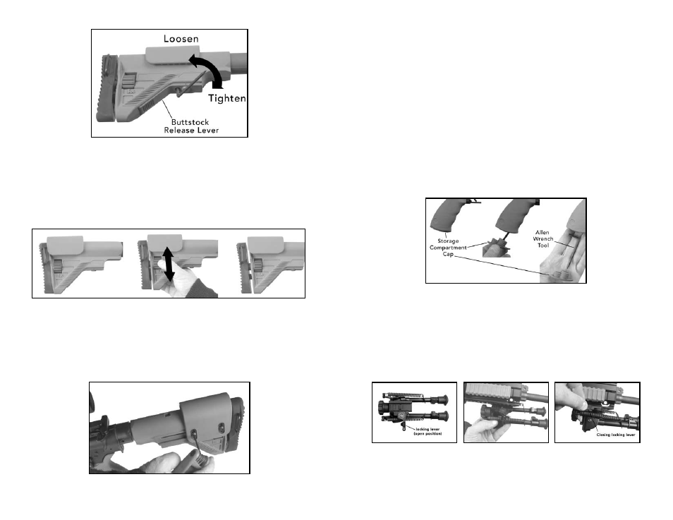
Fig. 66 – Fine adjustment of the buttstock
3. Adjusting the Length: Fine Adjustment (Fig. 67)
Fine adjustments to the length of the buttstock can be accomplished by engaging the
ambidextrous vertically mounted retention screw located at the rear of the buttstock.
When viewed from the rear, rotating the retention screw clockwise moves the recoil
pad to the rear and thus increases the length of pull. Rotating the retention screw
counterclockwise moves the recoil pad forward and thus decreases the length of pull.
An internal locking mechanism secures the recoil pad in the desired position and thus no
further steps are necessary once the proper adjustment has been achieved
Fig. 67 – Adjusting the Length, Fine Adjustment
4. Adjusting the Height (Fig. 68)
The MR762A1 LRP’s buttstock features an adjustable cheek piece that can be raised or
lowered. Loosen (but do not remove) the two small set screws located on the left hand
side of the cheek piece by rotating counterclockwise utilizing a 3 mm Allen Wrench. Four
horizontal reference marks are provided on each screw slot as a visual aid when aligning
the cheek piece after adjustment. Tighten the two small set screws clockwise once the
desired height of the cheek piece has been obtained.
Fig. 68 – Adjusting the Height
A unique mounting system that secures the cheek piece to a spring loaded locking plate
allows the cheek piece to remain stationary in relation to the receiver extension as the
entire buttstock is adjusted for length. This feature frees the operator to constantly having
to re-adjusting the cheek every time the buttstock is extended or retracted.
5. Miscellaneous Adjustments
A small spring loaded catch bolt, located on the bottom of the receiver extension, can
be used to minimize play between the extension and the buttstock while allowing the
operator the ability to adjust the length of pull. The buttstock must first be completely
removed from the receiver extension by pivoting downwards on the front of the release
lever while simultaneously sliding the stock off the extension.
Using a small straight slot screwdriver, rotate the slotted side of the catch bolt clockwise
using quarter-turn rotations until play between the two surfaces areas is minimized but still
allowing horizontal movement of the buttstock on the extension.
ERGO GRIP – The Ergo grip is already installed on the weapon. The Ergo grip provides
a comfortable grip surface well-suited for precision shooting. The special HK Allen wrench
tool for use in disassembly/separating the upper receiver from the lower receiver is also
stored in the grip’s storage compartment. For more information, see www.ergogrips.net.
Fig. 69 – ERGO Grip
BIPOD – Your MR762A1-LRP may already have the bipod attached. The bipod can be
moved to your desired location. It is recommended to attach the bipod between the
front-end to midway point of the lower Picatinny rail on the Free Floating Rail System of
the weapon.
Ensure the locking lever of the Quick Detach mount fits snug enough to hold the bipod
in place and not too tight so that the locking lever digs into the rail surface. The locking
lever of the mount can be adjusted as per the description below and using the included
Larue Tactical tool. For more information, visit www.laruetactical.com.
Fig. 70 – Bipod Locking
RAIL COvERS – The rail covers provide a solid grip in adverse conditions and protect
both the rail and the hand. They can be positioned on the Free Floating Rail System as
desired and where ever typical hand placement is desired. To remove them, simply peel